Arduino R4 Minima
This board features the R7FA4M1ABxCFM MCU with 256 KiB of FLASH and 32 KiB of SRAM running at 64 MHz (internal clock - HOCO).
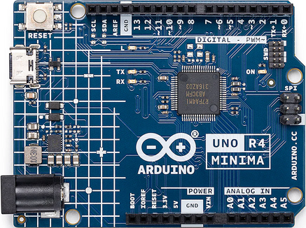
See the Arduino website for information about Arduino R4 Minima.
Buttons and LEDs
Buttons
There are no buttons on the Arduino R4 Minima board.
LEDs
There are three user-controllable LEDs on board the Arduino R4 Minima:
LED GPIO
L Amber LED P111 TX Yellow LED P012 RX Yellow LED P013
LED L is connected to ground and can be illuminated by driving the P111 output high. The TX and RX LEDs are pulled high and can be illuminated by driving the corresponding GPIO output low.
These LEDs are not used by the board port unless CONFIG_ARCH_LEDS is defined. In that case, the usage by the board port is defined in include/board.h and src/ra_autoleds.c. The LEDs are used to encode OS-related events as follows:
+-------------------+---------------------------+-------+------+------------+ | SYMBOL | MEANING | L | TX | RX | +===================+===========================+=======+======+============+ | LED_STARTED | > NuttX has been started | > OFF | OFF | > OFF | +-------------------+---------------------------+-------+------+------------+ | LED_HEAPALLOCATE | > Heap has been allocated | > OFF | OFF | > OFF | +-------------------+---------------------------+-------+------+------------+ | LED_IRQSENABLED | > Interrupts enabled | > OFF | OFF | > OFF | +-------------------+---------------------------+-------+------+------------+ | LED_STACKCREATED | > Idle stack created | > ON | OFF | > OFF | +-------------------+---------------------------+-------+------+------------+ | LED_INIRQ | > In an interrupt | > N/C | GLOW | > OFF | +-------------------+---------------------------+-------+------+------------+ | LED_SIGNAL | > In a signal handler | > N/C | GLOW | > OFF | +-------------------+---------------------------+-------+------+------------+ | LED_ASSERTION | > An assertion failed | > N/C | GLOW | > OFF | +-------------------+---------------------------+-------+------+------------+ | LED_PANIC | > The system has crashed | > N/C | N/C | > Blinking | +-------------------+---------------------------+-------+------+------------+ | LED_IDLE | > MCU is in sleep mode | > NA | NA | > NA | +-------------------+---------------------------+-------+------+------------+
Thus, if LED L is statically on, NuttX has successfully booted and is apparently running normally. If LED RX is glowing, then NuttX is handling interrupts (and also signals and assertions). If TX is flashing at approximately 2 Hz, then a fatal error has been detected, and the system has halted.
Serial Consoles
The R7FA4M1ABxCFM has a UART and 4 SCI (UARTs).
Any of the SCI interfaces may be used as a serial console. By default, SCI2 is used as the serial console in all configurations. This can be easily changed by modifying the configuration.
Arduino R4 Minima R7FA4M1ABxCFM Pin (Label) SCI Mapping ================== ============ 0 (RX0<-0) RXD2 1 (TX0->1) TXD2 13 (12) RXD9 14 (~11) TXD9 SWD-7 RXD1 SWD-8 TXD1
Loading Code
It is possible to use J-Link on the SWD connector or use USB Boot available through the USB-C connector.
RA USB Boot:
Reboot the board with BOOT shorted to GND and press the reset button twice (double click). The board will enumerate as "Renesas RA USB Boot."
Then, flash the nuttx.hex file using rfp-cli: (https://www.renesas.com/en/software-tool/renesas-flash-programmer-programming-gui)
Example command:
rfp-cli -device ra -port /dev/ttyACM0 -p ./build/nuttx.hexNote: Programming using the binary format will fail because, by default, the RA4M1 NuttX port writes to the .idcode section, which is located beyond the end of the flash area. This causes the RFP to attempt writing to protected regions, leading to failures.