ESP32-S3-Korvo-2 V3.0
chip:esp32, chip:esp32s3
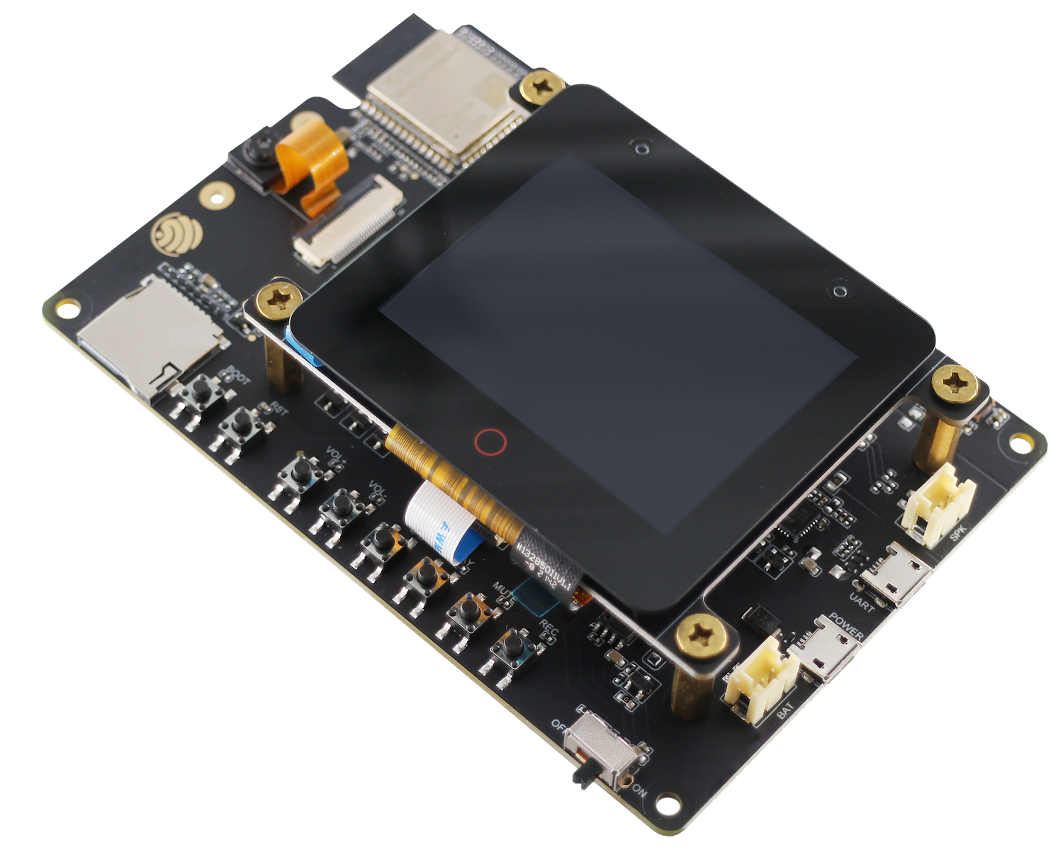
The ESP32-S3-Korvo-2 is a multimedia development board based on the ESP32-S3 chip. It is equipped with a two-microphone array which is suitable for voice recognition and near/far-field voice wake-up applications. The board integrates multiple peripherals such as LCD, camera, and microSD card. It also supports JPEG video stream processing. With all of its outstanding features, the board is an ideal choice for the development of low-cost and low-power network-connected audio and video products.
This board mainly consists of the following parts:
- Main board: ESP32-S3-Korvo-2
- LCD extension board: [ESP32-S3-Korvo-2-LCD <user-guide-esp32https://docs.espressif.com/projects/esp-adf/en/latest/design-guide/dev-boards/user-guide-esp32-s3-korvo-2-lcd.html>]
- Camera
This document is mostly dedicated to the main board. For detailed information on other parts, click the links above.
The document consists of the following sections:
- Getting started: Overview of the board and hardware/software setup instructions to get started.
- Hardware Reference: More detailed information about the board's hardware.
- Hardware Revision Details: Hardware revision history, known issues, and links to user guides for previous versions (if any) of the board.
- Related Documents: Links to related documentation.
Getting Started
This section provides a brief introduction of ESP32-S3-Korvo-2 V3.0, instructions on how to do the initial hardware setup and how to flash firmware onto it.
Description of Components
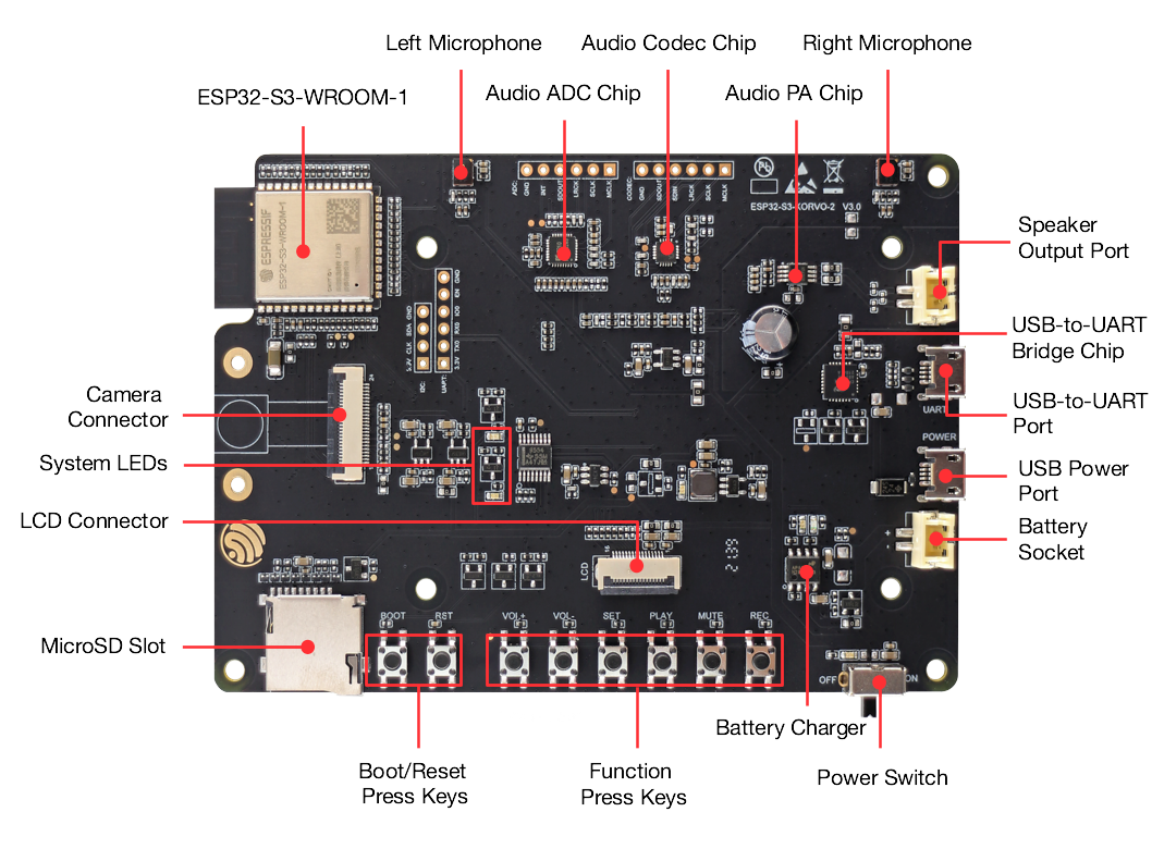
The key components of the board are described in a clockwise direction.
+--------------------+-------------------------------------------------+ | Key Component | Description | +====================+=================================================+ | ESP32-S3-WROOM-1 | The ESP32-S3-WROOM-1 is a powerful, generic | | Module | Wi-Fi + Bluetooth LE MCU module that is built | | | around the ESP32-S3 series of SoCs. On top of a | | | rich set of peripherals, the acceleration for | | | neural network computing and signal processing | | | workloads provided by the SoC make the modules | | | an ideal choice for a wide variety of | | | application scenarios related to AI and | | | Artificial Intelligence of Things (AIoT), such | | | as wake word detection, speech commands | | | recognition, face detection and recognition, | | | smart home, smart appliances, smart control | | | panel, smart speaker, etc. | +--------------------+-------------------------------------------------+ | Left Microphone | Onboard microphone connected to ADC. | +--------------------+-------------------------------------------------+ | Audio ADC Chip | [ES7210](h | | | ttp://www.everest-semi.com/pdf/ES7210%20PB.pdf) | | | is a high-performance, low-power 4-channel | | | audio analog-to-digital converter for | | | microphone array applications. It is very | | | suitable for music and speech applications. In | | | addition, ES7210 can also be used to collect | | | acoustic echo cancellation (AEC) echo reference | | | signals. | +--------------------+-------------------------------------------------+ | Audio Codec Chip | The audio codec chip, | | | [ES8311](ht | | | tp://www.everest-semi.com/pdf/ES8311%20PB.pdf), | | | is a low-power mono audio codec. It consists of | | | 1-channel ADC, 1-channel DAC, low noise | | | pre-amplifier, headphone driver, digital sound | | | effects, analog mixing, and gain functions. It | | | is interfaced with ESP32-S3-WROOM-1 module over | | | I2S and I2C buses to provide audio processing | | | in hardware independently from the audio | | | application. | +--------------------+-------------------------------------------------+ | Audio PA Chip | NS4150 is an EMI, 3 W mono Class D audio power | | | amplifier, amplifying audio signals from audio | | | codec chips to drive speakers. | +--------------------+-------------------------------------------------+ | Right Microphone | Onboard microphone connected to ADC. | +--------------------+-------------------------------------------------+ | Speaker Output | Output socket to connect a speaker. The 4-ohm | | Port | and 3-watt speaker is recommended. The pins | | | have a 2.00 mm/0.08" pitch. | +--------------------+-------------------------------------------------+ | USB-to-UART Bridge | A single chip USB-UART bridge CP2102N provides | | Chip | up to 3 Mbps transfer rates for software | | | download and debugging. | +--------------------+-------------------------------------------------+ | USB-to-UART Port | Functions as the communication interface | | | between a PC and the ESP32-S3-WROOM-1 module. | +--------------------+-------------------------------------------------+ | USB Power Port | Provides power to the board. It is recommended | | | to use at least 5V/2A power adapter to ensure a | | | stable power supply. | +--------------------+-------------------------------------------------+ | Battery Socket | Two pins socket to connect a single cell Li-ion | | | battery. | +--------------------+-------------------------------------------------+ | Power Switch | Power on/off knob: toggling it down powers the | | | board on; toggling it up powers the board off. | +--------------------+-------------------------------------------------+ | Battery Charger | AP5056 is a constant current and constant | | | voltage linear charger for single cell | | | lithium-ion batteries. Used for charging of a | | | battery connected to the Battery Socket over | | | the Micro USB Port. | +--------------------+-------------------------------------------------+ | Function Press | Six press keys labeled REC, MUTE, PLAY, SET, | | Keys | VOL- and VOL+. They are routed to | | | ESP32-S3-WROOM-1 module and intended for | | | development and testing of a UI for audio | | | applications using a dedicated API. | +--------------------+-------------------------------------------------+ | Boot/Reset Press | | Boot: holding down the Boot key and | | Keys | momentarily pressing the Reset key initiates | | | the firmware upload mode. Then you can upload | | | firmware through the serial port. | | | | Reset: pressing this button alone resets the | | | system. | +--------------------+-------------------------------------------------+ | MicroSD Slot | The development board supports a microSD card | | | in 1-bit mode, and can store or play audio | | | files in the microSD card. | +--------------------+-------------------------------------------------+ | LCD Connector | A FPC connector with 0.5 mm pitch to connect to | | | the LCD extension board. | +--------------------+-------------------------------------------------+ | System LEDs | Two general-purpose LEDs (green and red) | | | controlled by ESP32-S3-WROOM-1 module to | | | indicate certain operation states of the audio | | | application using dedicated API. | +--------------------+-------------------------------------------------+ | Camera Connector | An external camera module that can be connected | | | to the development board with the connector to | | | transmit images. | +--------------------+-------------------------------------------------+
Start Application Development
Before powering up your board, please make sure that it is in good condition with no obvious signs of damage.
Required Hardware
- 1 x ESP32-S3-Korvo-2 V3.0
- 1 x Speaker
- 2 x USB 2.0 cable (Standard-A to Micro-B)
Note
Be sure to use an appropriate USB cable. Some cables are for charging only and do not provide the needed data lines nor work for programming the boards.
Optional Hardware
- 1 x MicroSD card
- 1 x Li-ion battery
Note
Be sure to use a Li-ion battery that has a built-in protection circuit.
Hardware Setup
- Connect the speaker to the Speaker Output.
- Plug in the USB cables to the PC and to both USB ports of the board.
- The standby LED (green) should turn on. Assuming that a battery is not connected, the charging LED (red) will blink every couple of seconds.
- Toggle the Power Switch.
- The red Power On LED should turn on.
Contents and Packaging
The main board and its accessories can be ordered separately. The accessories include:
- LCD extension board: ESP32-S3-Korvo-2-LCD
- Camera
- Connectors:
- 20-pin FPC cable
- Fasteners:
- Copper standoffs (x8)
- Screws (x4)
Retail Orders
If you order a few samples, each board comes in an individual package in either antistatic bag or any packaging depending on your retailer.
For retail orders, please go to https://www.espressif.com/en/company/contact/buy-a-sample.
Wholesale Orders
If you order in bulk, the boards come in large cardboard boxes.
For wholesale orders, please go to https://www.espressif.com/en/contact-us/sales-questions.
Hardware Reference
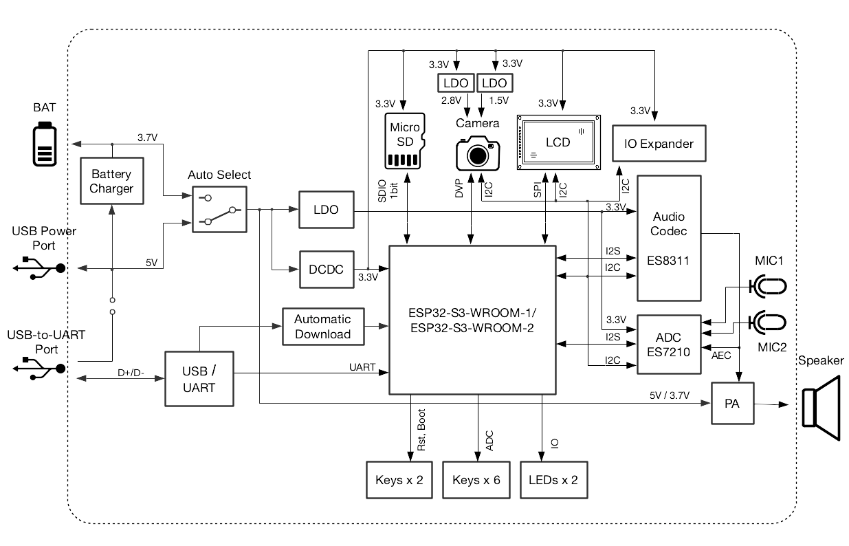
Block Diagram
The block diagram below shows the components of ESP32-S3-Korvo-2 V3.0 and their interconnections.
Notes on Power Distribution
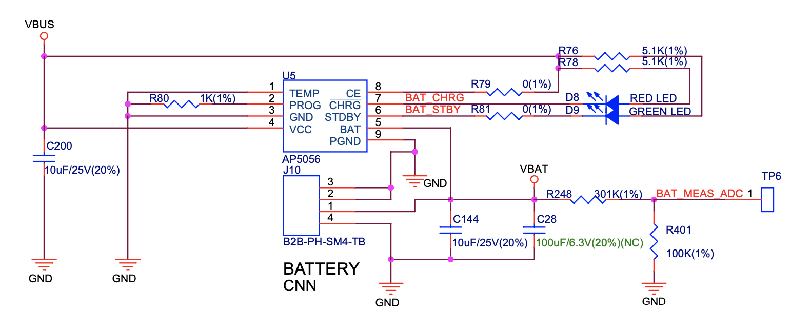
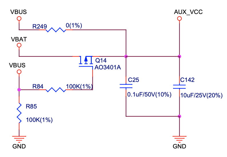
Power Supply over USB and from Battery
The main power supply is 5 V and provided by a USB. The secondary power supply is 3.7 V and provided by an optional battery. The USB power itself is fed with a dedicated cable, separating from a USB cable used for an application upload. To further reduce noise from the USB, the battery may be used instead of the USB.
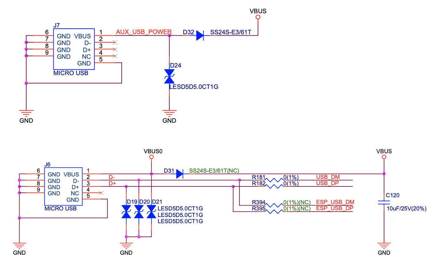
As shown in the figure below, if the USB power supply and battery power supply are connected at the same time with a high VBUS, an off-state Q14, and an automatic cut-off VBAT, the USB becomes the power supply for the system.
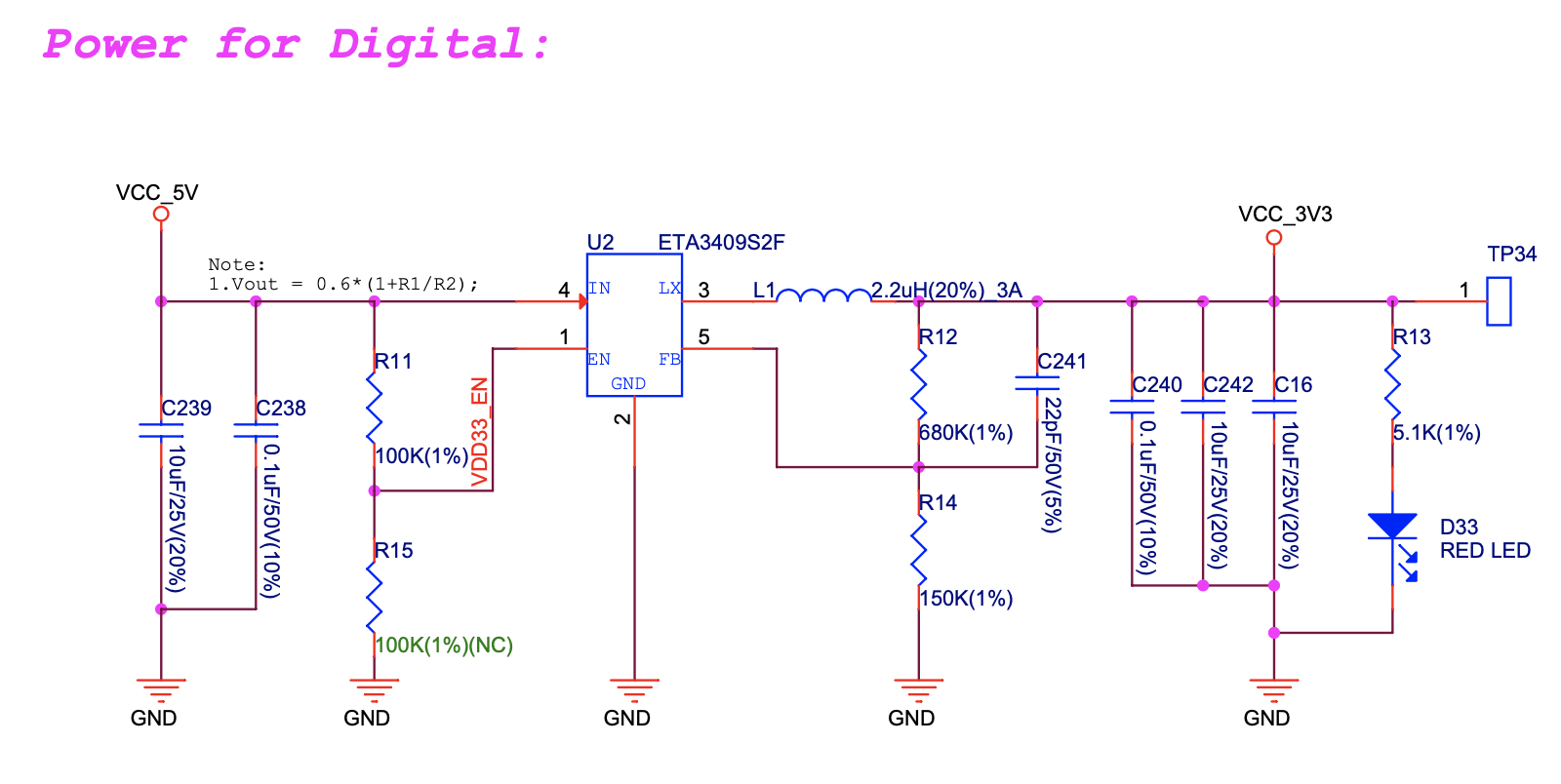
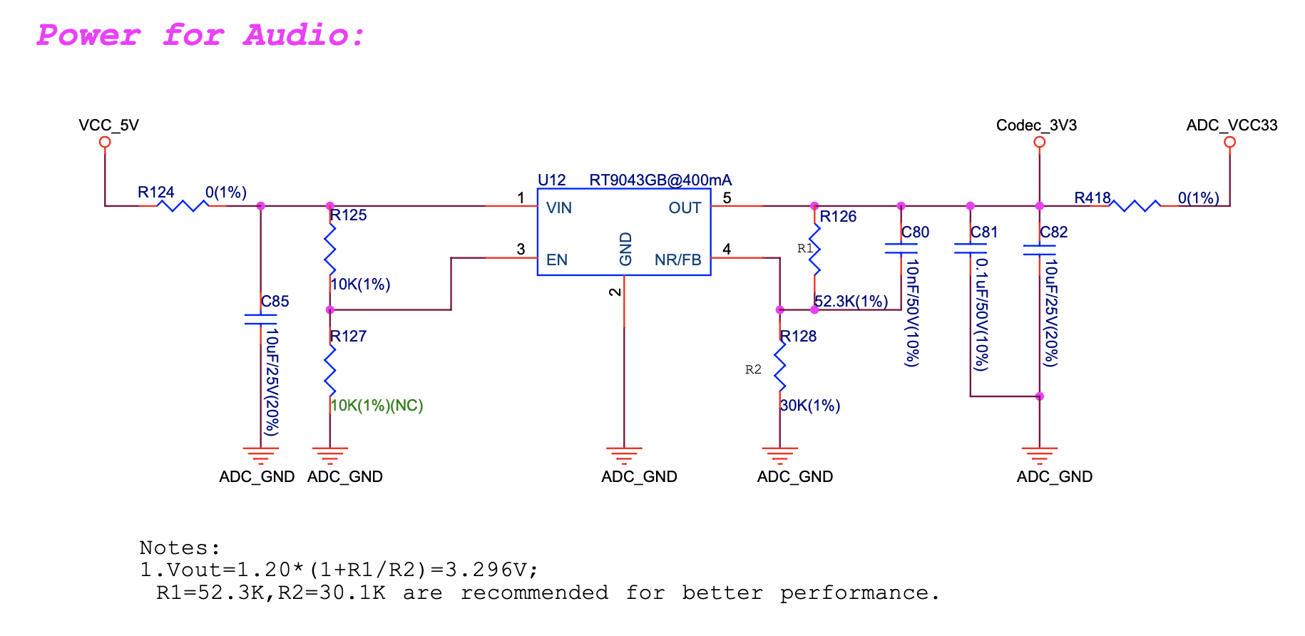
Independent Audio and Digital Power Supply
ESP32-S3-Korvo-2 V3.0 features independent power supplies to the audio components and ESP module. This should reduce noise in the audio signal from digital components and improve overall performance of the components.
GPIO Allocation Summary
The table below provides allocation of GPIOs exposed on terminals of ESP32-S3-WROOM-1 module to control specific components or functions of the board.
Pin[^1] Pin ES8311 ES7210 Camera LCD Keys MicroSD IO Other Name Expander
3 EN EN_KEY
4 IO4 DATA0
5 IO5 REC, MUTE,
PLAY, SET,
VOL-, VOL+
6 IO6 BAT_MEAS_ADC
7 IO7 CMD
8 IO15 CLK
9 IO16 I2S0_MCLK MCLK
10 IO17 I2C_SDA I2C_SDA SIOD TP_I2C_SDA I2C_SDA
11 IO18 I2C_CLK I2C_CLK SIOC TP_I2C_CLK I2C_CLK
12 IO8 I2S0_DSDIN
13 IO19 ESP_USB_DM (Reserve)
14 IO20 ESP_USB_DP (Reserve)
15 IO3 D5
16 IO46 NC
17 IO9 I2S0_SCLK SCLK
18 IO10 SDOUT
19 IO11 PCLK
20 IO12 D6
21 IO13 D2
22 IO14 D4
23 IO21 VSYNC
24 IO47 D3
25 IO48 PA_CTRL
26 IO45 I2S0_LRCK LRCK
27 IO0 LCD_SPI_SDA BOOT_KEY
28 IO35 NC
29 IO36 NC
30 IO37 NC
31 IO38 HREF
32 IO39 D9
33 IO40 XCLK
34 IO41 D8
35 IO42 D7
36 RXD0 ESP0_UART0_RX
37 TXD0 ESP0_UART0_TX
38 IO2 LCD_SPI_DC
39 IO1 LCD_SPI_CLK
41 EPAD
: ESP32-S3-WROOM-1 GPIO Allocation
The GPIOs allocated to the IO expander are further expanded to multiple GPIOs.
IO Expander Pin Pin Name LCD Other
4 P0 PA_CTRL
5 P1 LCD_CTRL
6 P2 LCD_RST
7 P3 LCD_CS
9 P4 TP_INT
10 P5 PERI_PWR_ON
11 P6 LED1
12 P7 LED2
: IO Expander GPIO Allocation
Connector
Camera Connector
No. Camera Signal ESP32-S3 Pin
1 SIOD GPIO17 2 SIOC GPIO18 3 D5 GPIO3 4 PCLK GPIO11 5 D6 GPIO12 6 D2 GPIO13 7 D4 GPIO14 8 VSYNC GPIO21 9 D3 GPIO47 10 HREF GPIO38 11 D9 GPIO39 12 XCLK GPIO40 13 D8 GPIO41 14 D7 GPIO42
LCD Connector
No. LCD Signal ESP32-S3 Pin
1 TP_I2C_SDA GPIO17 2 TP_I2C_CLK GPIO18 3 LCD_SPI_SDA GPIO0 4 LCD_SPI_DC GPIO2 5 LCD_SPI_CLK GPIO1
+-----+----------------+-------------+ | No. | LCD Signal | IO Expander | +=====+================+=============+ | 1 | ESP_LCD_CTRL | > P1 | +-----+----------------+-------------+ | 2 | ESP_LCD_RST | P2 | +-----+----------------+-------------+ | 3 | ESP_LCD_CS | P3 | +-----+----------------+-------------+ | 4 | ESP_TP_INT | P4 | +-----+----------------+-------------+
AEC Path
AEC path provides reference signals for AEC algorithm.
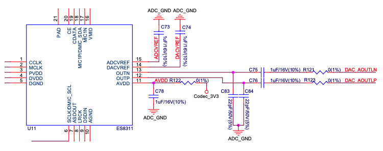
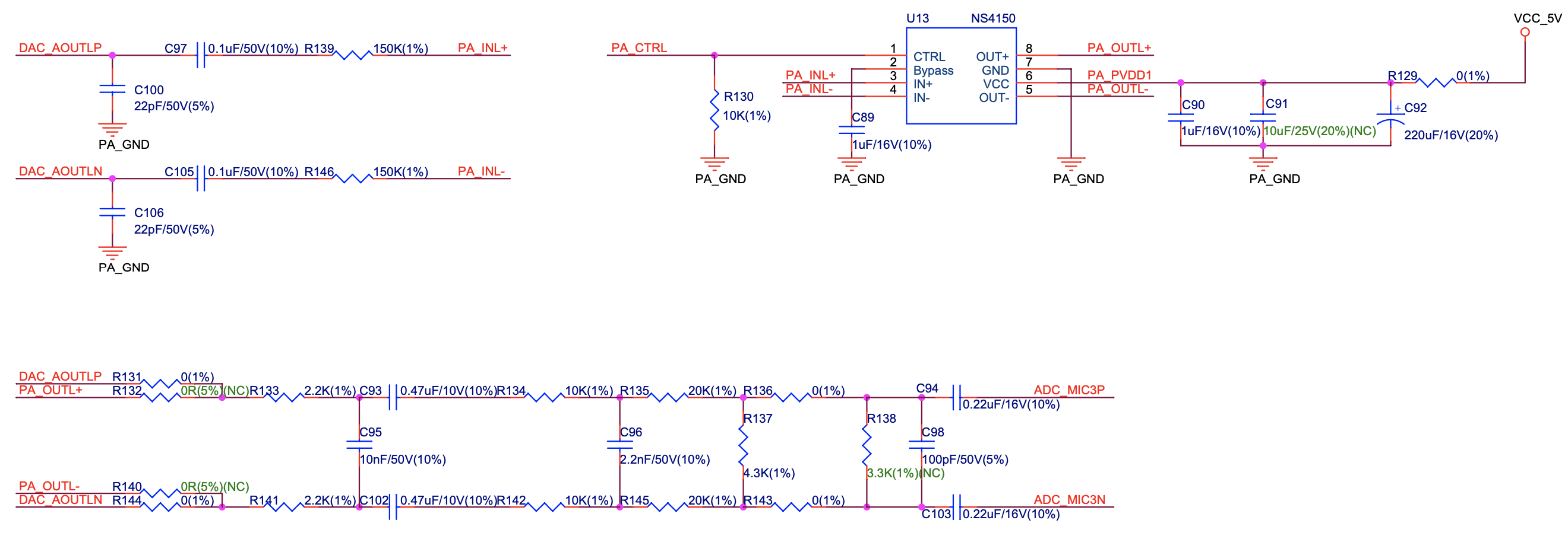
ESP32-S3-Korvo-2 provides two compatible echo reference signal source designs. One is Codec (ES8311) DAC output (DAC_AOUTLN/DAC_AOUTLP), the other is PA (NS4150) output (PA_OUTL+/PA_OUTL-). The former is the default and recommended selection. Resistors R132 and R140 marked NC (no component) in the figure below should not be installed.
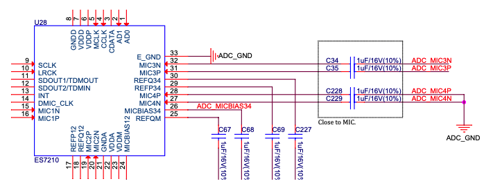
The echo reference signal is collected by ADC_MIC3P/ADC_MIC3N of ADC (ES7210) and then sent back to ESP32-S3 for AEC algorithm.
Hardware Setup Options
Using Automatic Upload
Entering of the ESP board into upload mode may be done in two ways:
- Manually by pressing both Boot and RST keys and then releasing first RST and then Boot key.
- Automatically by software performing the upload. The software is using DTR and RTS signals of the serial interface to control states of EN and IO0 of the ESP board. For details see ESP32-S3-Korvo-2 V3.0 Schematic (PDF).
Allocation of ESP Pins to Test Points
This section describes the allocation of test points available on the ESP32-S3-Korvo-2 V3.0 board.
The test points are bare through hole solder pads and have a standard 2.54 mm/0.1" pitch. You may need to populate them with pin headers or sockets for easy connection of external hardware.
Codec Test Point/J15
No. Codec Pin ESP32-S3 Pin
1 MCLK GPIO16 2 SCLK GPIO9 3 LRCK GPIO45 4 DSDIN GPIO8 5 ASDOUT -- 6 GND --
ADC Test Point/J16
No. ADC Pin ESP32-S3 Pin
1 MCLK GPIO16 2 SCLK GPIO9 3 LRCK GPIO45 4 SDOUT GPIO10 5 INT -- 6 GND --
UART Test Point/J17
No. UART Pin
1 3.3V 2 TXD 3 RXD 4 IO0 5 EN 6 GND
I2C Test Point/J18
No. I2C Pin ESP32-S3 Pin
1 3.3V -- 2 CLK GPIO18 3 SDA GPIO17 4 GND --
Hardware Revision Details
This is the first revision of this board released.
Related Documents
- ESP32-S3 Series Datasheet (PDF)
- ESP32-S3-WROOM-1/1U Datasheet (PDF)
- ESP32-S3-Korvo-2 V3.0 Schematic (PDF)
- ESP32-S3-Korvo-2 V3.0 PapplicationsCB Layout (PDF)
For further design documentation for the board, please contact us at sales@espressif.com.
Configurations
All of the configurations presented below can be tested by running the following commands:
 ./tools/configure.sh esp32s3-korvo-2:<config_name>
 make flash ESPTOOL_PORT=/dev/ttyUSB0 -j(nproc)
Where <config_name> is the name of board configuration you want to use, i.e.: nsh, buttons, wifi... Then use a serial console terminal like picocom configured to 115200 8N1.
audio
This configuration uses the I2S peripheral and the ES8311 audio codec to play an audio file.
Simple HTTP server
Prepare a PCM-encoded ([.wav]{.title-ref}) audio file with 16 or 24 bits/sample (sampled at 16~48kHz). This file must be placed into a folder in a computer that could be accessed on the same Wi-Fi network the ESP32 will be connecting to.
Python provides a simple HTTP server. cd to the audio file folder on the PC and run:
 python3 -m http.server
Serving HTTP on 0.0.0.0 port 8000 (http://0.0.0.0:8000/)
Look for your PC IP address and test playing the prepared audio on your browser:
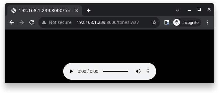
After successfully built and flashed, connect the board to the Wi-Fi network:
nsh> wapi psk wlan0 mypasswd 3
nsh> wapi essid wlan0 myssid 1
nsh> renew wlan0
Once connected, open NuttX's player and play the file according to the filename and the IP address of the HTTP server:
nsh> nxplayer
nxplayer> play http://192.168.1.239:8000/tones.wav
nsh
Basic NuttShell configuration (console enabled in UART0, exposed via USB connection by means of CP2102 converter, at 115200 bps).
rtptools
RTP Tools is a set of small applications that can be used for processing RTP data.
rtpplay: play-back RTP sessions recorded byrtpdumprtpsend: generate RTP packets from the textual description, generated by hand orrtpdumprtpdump: parse and print RTP packets, generating output files suitable forrtpplayandrtpsendrtptrans: RTP translator between unicast and multicast networks
This set of tools enables receiving RTP packets and writing the content to a FIFO. nxplayer then reads from the FIFO, enabling using NuttX as a RTP receiver for audio applications.
This is particularly useful to stream uncompressed audio through Wi-Fi to remote speakers.
sdmmc
Based on nsh. Support for sdmmc driver is enabled with following settings:
Enable sdmmc driver:
CONFIG_ESP32S3_SDMMC=y
GPIO definitions:
CONFIG_ESP32S3_SDMMC_CMD=7
CONFIG_ESP32S3_SDMMC_CLK=15
CONFIG_ESP32S3_SDMMC_D0=4
ESP32-S3-Korvo-2's MicroSD supports only one data port:
CONFIG_SDIO_WIDTH_D1_ONLY=y
Multiblock limitation due to hardware:
CONFIG_MMCSD_MULTIBLOCK_LIMIT=128
Use sched_yield instead of usleep due to long tick time:
CONFIG_MMCSD_CHECK_READY_STATUS_WITHOUT_SLEEP=y
Format and mount the SD/MMC device with following commands:
mkfatfs -F 32 -r /mnt /dev/mmcsd1
mount -t vfat /dev/mmcsd1 /mnt
FAT filesystem is enabled in the default configuration. Other filesystems may also work.
Connect to your Network
Connect the ESP32-S3-Korvo-2 board to your network to be able to receive RTP packets:
nsh> wapi psk wlan0 mypasswd 3
nsh> wapi essid wlan0 myssid 1
nsh> renew wlan0
nsh> ifconfig
wlan0   Link encap:Ethernet HWaddr aa:bb:cc:dd:ff:ee at RUNNING mtu 1504
        inet addr:192.168.1.38 DRaddr:192.168.1.1 Mask:255.255.255.0

            IPv4   TCP   UDP  ICMP
Received     00d5  0000  00d4  0000
Dropped      0001  0000  0000  0000
IPv4        VHL: 0000   Frg: 0000
Checksum   0000  0000  0000  ----
TCP         ACK: 0000   SYN: 0000
            RST: 0000  0000
Type       0000  ----  ----  0000
Sent         0002  0000  0002  0000
Rexmit     ----  0000  ----  ----
Please, check your device's IP (192.168.1.38 in this example): RTP packets will be sent to it.
Sending Audio through pulseaudio
pulseaudio is able to send RTP packets through the network:
pactl load-module module-null-sink sink_name=rtp format=s16be channels=2 rate=44100 sink_properties="device.description='RTP'"
pactl load-module module-rtp-send source=rtp.monitor format=s16le destination_ip=192.168.1.38 port=46998
The loaded sink is used to send PC audio through RTP, using the 192.168.1.38:46998 (boards's IP in this example, please adjust accordingly).
Receiving the RTP packets
RTP packets will be written to a FIFO: create the FIFO and run rtpdump on background:
nsh> mkfifo temp
nsh> rtpdump -F payload -o temp /46998 &
rtpdump [31:100]
Playing Audio
Finally, run nxplayer to play from the FIFO:
nsh> nxplayer
NxPlayer version 1.05
h for commands, q to exit

nxplayer> playraw temp 2 16 44100
This board contains the ES8311 audio codec. Please attach your passive loudspeaker to the Speaker Output Port to listen to the audio content streamed through the Wi-Fi in CD quality!
[^1]: Pin - ESP32-S3-WROOM-1 module pin number, GND and power supply pins are not listed.