ESP32 DevKitC
chip:esp32, chip:esp32wroom32
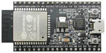
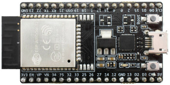
The ESP32 DevKitC is a development board for the ESP32 SoC from Espressif, based on a ESP-WROOM-32 module. You can find the original V2 version and the newer V4 variant. They are pin compatible.
Features
- ESP32 WROOM Module
- USB-to-UART bridge via micro USB port
- Power LED
- EN and BOOT buttons (BOOT accessible to user)
- SPI FLASH (size varies according to model
Serial Console
UART0 is, by default, the serial console. It connects to the on-board CP2102 converter and is available on the USB connector USB CON8 (J1).
It will show up as /dev/ttypUSB[n] where [n] will probably be 0 (is it 1 on my PC because I have a another device at ttyUSB0).
Buttons and LEDs
Board Buttons
There are two buttons labeled Boot and EN. The EN button is not available to software. It pulls the chip enable line that doubles as a reset line.
The BOOT button is connected to IO0. On reset it is used as a strapping pin to determine whether the chip boots normally or into the serial bootloader. After reset, however, the BOOT button can be used for software input.
Board LEDs
There are several on-board LEDs for that indicate the presence of power and USB activity. None of these are available for use by software.
Ethernet
ESP32 has a 802.11 hardware MAC, so just connects to external PHY chip. Due to the limited number of GPIOs in ESP32, it's recommended to use RMII to connect to an external PHY chip. Current driver also only supports RMII option.
The RMII GPIO pins are fixed, but the SMI and functional GPIO pins are optional.
RMII GPIO pins are as following:
ESP32 GPIO PHY Chip GPIO
IO25 RXD[0] IO26 RXD[1] IO27 CRS_DV IO0 REF_CLK IO19 TXD[0] IO21 TX_EN IO22 TXD[1]
SMI GPIO pins (default option) are as following:
ESP32 GPIO PHY Chip GPIO
IO18 MDIO IO23 MDC
Functional GPIO pins(default option) are as following:
ESP32 GPIO PHY Chip GPIO
IO5 Reset_N
Espressif has an official Ethernet development board.
This driver has been tested according to this board and ESP32 core board
- LAN8720 module. If users have some issue about using this driver, please refer the upper official document, specially the issue that GPIO0 causes failing to bring the ESP32 chip up.
I2S
ESP32 has two I2S peripherals accessible using either the generic I2S audio driver or a specific audio codec driver (CS4344 bindings are available at the moment). The generic I2S audio driver enables using both the receiver module (RX) and the transmitter module (TX) without using any specific codec. Also, it's possible to use the I2S character device driver to bypass the audio subsystem and write directly to the I2S peripheral.
Note
The I2S peripheral is able to work on two functional modes internally: 16 and 32-bit width. ESP32's I2S driver, however, uses an internal buffer to enable inserting padding bytes and provide the ability to play 8, 16, 24 or 32-bits/sample audio files. Sample rate and data width are automatically set by the upper half audio driver.
Note
Also, it's possible to use 8, 16, 24, and 32-bit-widths writing directly to the I2S character device. Just make sure to set the bit-width:
make menuconfig
-> System Type
:
-\> ESP32 Peripheral Selection

:

    -\> I2S

    :

        -\> I2S0/1

        :   -\> Bit Width
And make sure the data stream buffer being written to the I2S peripheral is aligned to the next boundary i.e. 16 bits for the 8 and 16-bit-widths and 32 bits for 24 and 32-bit-widths.
The following configurations use the I2S peripheral::
: - platforms/xtensa/esp32/boards/esp32-devkitc/index:audio{.interpreted-text role="ref"} - platforms/xtensa/esp32/boards/esp32-devkitc/index:i2schar{.interpreted-text role="ref"} - platforms/xtensa/esp32/boards/esp32-devkitc/index:nxlooper{.interpreted-text role="ref"}
Pin Mapping
To be updated
Pin Signal Notes
? ? ?
Configurations
All of the configurations presented below can be tested by running the following commands:
 ./tools/configure.sh esp32-devkitc:<config_name>
 make flash ESPTOOL_PORT=/dev/ttyUSB0 -j
Where <config_name> is the name of board configuration you want to use, i.e.: nsh, buttons, wifi... Then use a serial console terminal like picocom configured to 115200 8N1.
adc
The adc configuration enables the ADC driver and the ADC example application. ADC Unit 1 is registered to /dev/adc0 with channels 0, 3 and 4 enabled by default. Currently, the ADC operates in oneshot mode.
More ADC channels can be enabled or disabled in ADC Configuration menu.
This example shows channels 0 and 4 connected to GND and channel 3 to 3.3 V (all readings show in units of mV):
nsh> adc -n 1
adc_main: g_adcstate.count: 1
adc_main: Hardware initialized. Opening the ADC device: /dev/adc0
Sample:
1: channel: 0 value: 142
2: channel: 3 value: 3441
3: channel: 4 value: 142
audio
This configuration uses the I2S0 peripheral and an externally connected audio codec to play an audio file streamed over an HTTP connection while connected to a Wi-Fi network.
Audio Codec Setup
The CS4344 audio codec is connected on the following pins:
ESP32 Pin CS4344 Pin Description
0 MCLK Master Clock 4 SCLK Serial Clock 5 LRCK Left Right Clock (Word Select) 18 SDIN Serial Data In on CS4344. (DOUT on ESP32)
Simple HTTP server
Prepare a PCM-encoded ([.wav]{.title-ref}) audio file with 16 or 24 bits/sample (sampled at 16~48kHz). This file must be placed into a folder in a computer that could be accessed on the same Wi-Fi network the ESP32 will be connecting to.
Python provides a simple HTTP server. cd to the audio file folder on the PC and run:
 python3 -m http.server
Serving HTTP on 0.0.0.0 port 8000 (http://0.0.0.0:8000/)
Look for your PC IP address and test playing the prepared audio on your browser:
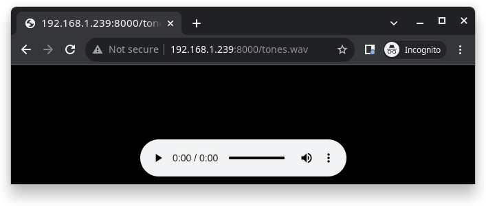
After successfully built and flashed, connect the board to the Wi-Fi network:
nsh> wapi psk wlan0 mypasswd 3
nsh> wapi essid wlan0 myssid 1
nsh> renew wlan0
Once connected, open NuttX's player and play the file according to its file name and the IP address of the HTTP server:
nsh> nxplayer
nxplayer> play http://192.168.1.239:8000/tones.wav
autopm
This configuration makes the device automatically enter the low power consumption mode when in the idle state, powering off the cpu and other peripherals.
In minimum power save mode, the station wakes up every DTIM to receive a beacon. The broadcast data will not be lost because it is transmitted after DTIM. However, it can not save much more power if DTIM is short as the DTIM is determined by the access point.
ble
This configuration is used to enable Bluetooth Low Energy support for this board. You can scan for Bluetooth devices using the following commands:
NuttShell (NSH) NuttX-10.2.0
nsh> ifconfig
bnep0   Link encap:UNSPEC at DOWN
        inet addr:0.0.0.0 DRaddr:0.0.0.0 Mask:0.0.0.0
wlan0   Link encap:Ethernet HWaddr ac:67:b2:53:8b:ec at UP
        inet addr:10.0.0.2 DRaddr:10.0.0.1 Mask:255.255.255.0
nsh> bt bnep0 scan start
nsh> bt bnep0 scan stop
nsh> bt bnep0 scan get
Scan result:
1.     addr:           63:14:2f:b9:9f:83 type: 1
      rssi:            -90
      response type:   3
      advertiser data: 1e ff 06 00 01 09 20 02 7c 33 a3 a7 cd c9 44 5b
2.     addr:           52:ca:05:b5:ad:77 type: 1
      rssi:            -82
      response type:   3
      advertiser data: 1e ff 06 00 01 09 20 02 03 d1 21 57 bf 19 b3 7a
3.     addr:           46:8e:b2:cd:94:27 type: 1
      rssi:            -92
      response type:   2
      advertiser data: 02 01 1a 09 ff c4 00 10 33 14 12 16 80 02 0a d4
4.     addr:           46:8e:b2:cd:94:27 type: 1
      rssi:            -92
      response type:   4
      advertiser data: 18 09 5b 4c 47 5d 20 77 65 62 4f 53 20 54 56 20
5.     addr:           63:14:2f:b9:9f:83 type: 1
      rssi:            -80
      response type:   3
    advertiser data: 1e ff 06 00 01 09 20 02 7c 33 a3 a7 cd c9 44 5b
blewifi
Combines the capabilities of the ble and wifi configurations. ESP32 has only one 2.4 GHz ISM band RF module, which is shared by Bluetooth (BT & BLE) and Wi-Fi, so Bluetooth can't receive or transmit data while Wi-Fi is receiving or transmitting data and vice versa. Under such circumstances, ESP32 uses the time-division multiplexing method to receive and transmit packets.
bmp280
This configuration enables the use of the BMP280 temperature and pressure sensor over I2C. You can check that the sensor is working by using the sensortest application:
nsh> sensortest baro0
baro0: timestamp:66870000 value1:1008.37 value2:31.70
baro0: timestamp:66890000 value1:1008.31 value2:31.70
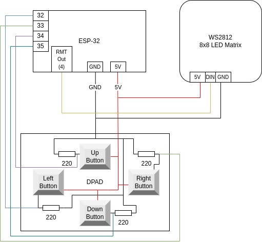
brickmatch
This configuration enables brickmatch game using LCD screen (APA102) and gesture sensor (APDS9960). Alternatively, you can use led matrix (ws2812) by enabling [GAMES_BRICKMATCH_USE_LED_MATRIX]{.title-ref} option for output device. Also for input device selection you can enable [GAMES_BRICKMATCH_USE_DJOYSTICK]{.title-ref} to use joystick, [GAMES_BRICKMATCH_USE_GPIO]{.title-ref} to use gpio and [GAMES_BRICKMATCH_USE_CONSOLEKEY]{.title-ref} to use serial console.
You can run the game by using brick command:
nsh> brick
Here is the sample wiring diagram that demonstrates how to wire ws2812 with buttons for brickmatch example:
buttons
This configuration shows the use of the buttons subsystem. It can be used by executing the buttons application and pressing on any of the available board buttons:
nsh> buttons
buttons_main: Starting the button_daemon
buttons_main: button_daemon started
button_daemon: Running
button_daemon: Opening /dev/buttons
button_daemon: Supported BUTTONs 0x01
nsh> Sample = 1
Sample = 0
capture
The capture configuration enables the capture driver and the capture example, allowing the user to measure duty cycle and frequency of a signal. Default pin is GPIO 14 with an internal pull-up resistor enabled. When connecting a 50 Hz pulse with 50% duty cycle, the following output is expected:
nsh> cap
cap_main: Hardware initialized. Opening the capture device: /dev/capture0
cap_main: Number of samples: 0
pwm duty cycle: 50 %
pwm frequency: 50 Hz
pwm duty cycle: 50 %
pwm frequency: 50 Hz
coremark
This configuration sets the CoreMark benchmark up for running on the maximum number of cores for this system. It also enables some optimization flags and disables the NuttShell to get the best possible score.
Note
As the NSH is disabled, the application will start as soon as the system is turned on.
cxx
Development environment ready for C++ applications. You can check if the setup was successful by running cxxtest:
nsh> cxxtest
Test ofstream ================================
printf: Starting test_ostream
printf: Successfully opened /dev/console
cout: Successfully opened /dev/console
Writing this to /dev/console
Test iostream ================================
Hello, this is only a test
Print an int: 190
Print a char: d
Test std::vector =============================
v1=1 2 3
Hello World Good Luck
Test std::map ================================
Test C++17 features ==========================
File /proc/meminfo exists!
Invalid file! /invalid
File /proc/version exists!
dac
This configuration enables DAC and registers a DAC example application.
Note
The DAC module is hard-wired to pins 25 (channel 0) and 26 (channel 1). The default device name is /dev/dac0 and can be changed in the config menu.
Note
The DAC channels in IDF are numbered channel 1 (pin 25) and channel 2 (pin 26).
Note
Max value 255 should be close to VRef (3.3V) but it probably will not. You can more realistically expect to get voltage around 3.09V.
With this example you can use (not only) the following commands:
For a multimeter, you can use the command:
dac -d 5000 -s 32 test
For oscilloscope or anything else with tracing:
dac -d 0 -s 4 test
For more info about the example capabilities invoke help message by typing
dac -h
efuse
A wifi configuration with the eFuse driver enabled. It can be accessed through the /dev/efuse device file.
elf
This configuration uses apps/examples/elf in order to test the ELF loader. It can be tested by executing the elf application.
espnow
WARNING: espnow and wifi are using the same hardware on the esp32. When a connection to a accespoint is made while espnow is operational the espnow connection will break if the accesspoint wants to use a different wifi channel.
A espnow setup can be used to create a 6lowpan network of esp32 nodes. A sample configuration is found in esp32-devkitc:espnow. The node address can be changed under ESP32 Peripherals option Espnow. The node address is direct related to the ipv6 address of the node. Changing the ipv6 address also changes the node address.
To test the communication using udpserver and udpclient two nodes need to be prepared with different ipv6 address.
The server node is assigned the node address 0x000a and the udp server is started using:
The client node can use the default node address (0xfffe) and the updclient can be started using:
The server node will show the incoming messages:
The sample configuration also allows a telnet session over espnow:
On the server (node 0x000a):
On the client (node Oxfffe):
i2schar
This configuration enables the I2S character device and the i2schar example app, which provides an easy-to-use way of testing the I2S peripherals (I2S0 and I2S1), enabling both the TX and the RX for those peripherals.
I2S0 pinout
ESP32 Pin Signal Pin Description
0 MCLK Master Clock 4 BCLK Bit Clock (SCLK) 5 WS Word Select (LRCLK) 18 DOUT Data Out 19 DIN Data IN
I2S1 pinout
ESP32 Pin Signal Pin Description
22 BCLK Bit Clock (SCLK) 23 WS Word Select (LRCLK) 25 DOUT Data Out 26 DIN Data IN
After successfully built and flashed, run on the boards's terminal:
i2schar -p /dev/i2schar[0-1]
The corresponding output should show related debug information.
knsh
This is identical to the nsh configuration except that (1) NuttX is built as PROTECTED mode, monolithic module and the user applications are built separately and, as a consequence, (2) some features that are only available in the FLAT build are disabled.
Protected Mode support for ESP32 relies on the PID Controller peripheral for implementing isolation between Kernel and Userspace.
By working together with the MMU and Static MPUs of the ESP32, the PID Controller is able to restrict the application access to peripherals, on-chip memories (Internal ROM and Internal SRAM) and off-chip memories (External Flash and PSRAM).
Warning
* The PID Controller driver is in EXPERIMENTAL state, so please consider the Protected Mode feature for ESP32 a Proof-of-Concept. * The PID Controller does not prevent the application from accessing CPU System Registers.
leds
This configuration uses the on-board LED (or an external LED connected to GPIO2) to demonstrate the use of the userleds subsystem:
nsh> leds
leds_main: Starting the led_daemon
leds_main: led_daemon started
led_daemon (pid# 3): Running
led_daemon: Opening /dev/userleds
led_daemon: Supported LEDs 0x01
led_daemon: LED set 0x01
led_daemon: LED set 0x00
led_daemon: LED set 0x01
led_daemon: LED set 0x00
led_daemon: LED set 0x01
max6675
This configuration enables the use of the MAX6675 temperature sensor over SPI. The following pin configuration is used to connect the sensor:
Pin Signal
15 CS 14 SCK 12 MISO
You can check that the sensor is working by using the max6675 application:
nsh> max6675
Unable to open file /dev/temp1
Unable to open file /dev/temp2
Unable to open file /dev/temp3
Starting...
Channel SSP0/SPI1 Device 0: Temperature = 24!
Channel SSP0/SPI1 Device 1: Not enabled!
Channel SSP1/SPI2 Device 0: Not enabled!
Channel SSP1/SPI2 Device 1: Not enabled!
mcp2515
This config is used to communicate with MCP2515 CAN over SPI chip. SPI3 is used and kept with the default IOMUX pins, i.e.:
Pin Signal
5 CS 18 SCK 23 MOSI 19 MISO
The MCP2515 interrupt (INT) pin is connected to the pin 22 of the ESP32-Devkit.
mcuboot_nsh
This configuration is the same as the nsh configuration, but it generates the application image in a format that can be used by MCUboot. It also makes the make bootloader command to build the MCUboot bootloader image using the Espressif HAL.
mcuboot_slot_confirm
This configuration is used to represent an MCUboot update image that needs to be confirmed after flashing. The image can be confirmed by using the following command:
nsh> mcuboot_confirm
Application Image successfully confirmed!
For more information, check this demo.
mcuboot_update_agent
This configuration is used to represent an MCUboot image that contains an update agent to perform OTA updates. First, you will have to setup a HTTP server to provide the update image. To do that, we can run a simple Python server on the same folder that contains our binary file on the computer:
sudo python -m http.server 8080
After this, we can use NSH to connect to our network and use the agent to perform the firmware update:
nsh> ifup wlan0
nsh> wapi mode wlan0 2
nsh> wapi psk wlan0 mypasswd 3
nsh> wapi essid wlan0 myssid 1
nsh> renew wlan0
nsh> mcuboot_agent http://<SERVER_IP>:8080/nuttx.bin
For more information, check this demo.
modbus
This configurations shows how to use this device as a ModBus RTU Slave. After configuring the desired pins on menuconfig and wiring the RS485 converter, you can enable the ModBus to respond to queries:
nsh> modbus -e
Now you will be able to read the ModBus registers using an application like mbpoll. For more information, check this video.
module
This config is to run apps/examples/module.
motor
The motor configuration enables the MCPWM peripheral with support to brushed DC motor control.
It creates a /dev/motor0 device with speed and direction control capabilities by using two GPIOs (GPIO15 and GPIO16) for PWM output. PWM frequency is configurable from 25 Hz to 3 kHz, however it defaults to 1 kHz. There is also support for an optional fault GPIO (defaults to GPIO10), which can be used for quick motor braking. All GPIOs are configurable in menuconfig.
mqttc
This configuration tests the MQTT-C publisher example.
From the host, start the broker and subscribe to the test topic. Using mosquitto this should be:
 mosquitto&
 mosquitto_sub -t test
From the NSH, connect to an access point:
nsh> wapi psk wlan0 mypasswd 3
nsh> wapi essid wlan0 myssid 1
nsh> renew wlan0
Publish to the broker:
nsh> mqttc_pub -h 192.168.1.11
The default behavior is to publish the message test. The following should be outputted:
nsh> mqttc_pub -h 192.168.1.11
     Success: Connected to broker!
     Success: Published to broker!

     Disconnecting from 192.168.1.11
From the host the message test should be outputted.
ms5611
This configuration enables the use of the MS5611 pressure sensor over I2C. You can check that the sensor is working by using the sensortest application:
nsh> sensortest baro0
baro0: timestamp:66870000 value1:1008.37 value2:31.70
baro0: timestamp:66890000 value1:1008.31 value2:31.70
nsh
Basic NuttShell configuration (console enabled in UART0, exposed via USB connection by means of CP2102 converter, at 115200 bps).
nxdiag
This configuration enables the NuttX diagnostics tool. By default, it will gather information about the NuttX system, its configuration, the compilation and linking flags used, the host system PATH and Espressif specific information. It can be used by executing the nxdiag application:
nsh> nxdiag --all
Nxdiag Report:

NuttX RTOS info:
        Hostname:
        Release: 10.4.0
        Build: 75e13a67ba-dirty May 24 2023 14:53:27
        Arch: xtensa
        Config: esp32-devkitc:nxdiag

NuttX CFLAGS:
        -fno-common
        -Wall
        ...
nxlooper
This configuration uses the I2S1 peripheral as an I2S receiver and the I2S0 peripheral as an I2S transmitter. The idea is to capture an I2S data frame using an I2S peripheral and reproduce the captured data on the other.
Receiving data on I2S1
The I2S1 will act as a receiver (master mode), capturing data from DIN, which needs to be connected to an external source as follows:
ESP32 Pin Signal Pin Description
22 BCLK Bit Clock (SCLK) 23 WS Word Select (LRCLK) 26 DIN Data IN
Transmitting data on I2S0
The I2S0 will act as a transmitter (master mode), replicating the data captured on I2S1. The pinout for the transmitter is as follows:
ESP32 Pin Signal Pin Description
0 MCLK Master Clock 4 BCLK Bit Clock (SCLK) 5 WS Word Select (LRCLK) 18 DOUT Data Out
Note
The audio codec CS4344 can be connected to the transmitter pins to reproduce the captured data if the receiver's source is an audio data.
nxlooper
The nxlooper application captures data from the audio device with receiving capabilities (the I2S1 on this example) and forwards the audio data frame to the audio device with transmitting capabilities (the I2S0 on this example).
After successfully built and flashed, run on the boards' terminal:
nsh> nxlooper
nxlooper> loopback
Note
loopback command default arguments for the channel configuration, the data width and the sample rate are, respectively, 2 channels, 16 bits/sample and 48KHz. These arguments can be supplied to select different audio formats, for instance:
nxlooper> loopback 2 8 44100
oneshot
This config demonstrate the use of oneshot timers present on the ESP32. To test it, just run the oneshot example:
nsh> oneshot
Opening /dev/oneshot
Maximum delay is 4294967295999999
Starting oneshot timer with delay 2000000 microseconds
Waiting...
Finished
ostest
This is the NuttX test at apps/testing/ostest that is run against all new architecture ports to assure a correct implementation of the OS. The default version is for a single CPU but can be modified for an SMP test by adding:
CONFIG_SMP=y
CONFIG_SMP_NCPUS=2
CONFIG_SPINLOCK=y
pm
This configuration enables the CPU power management through governors.
psram
This config tests the PSRAM driver over SPIRAM interface. You can use the ramtest command to test the PSRAM memory. We are testing only 64KB on this example (64 * 1024), but you can change this number to 2MB or 4MB depending on PSRAM chip used on your board:
nsh> ramtest -w 0x3F800000 65536
RAMTest: Marching ones: 3f800000 65536
RAMTest: Marching zeroes: 3f800000 65536
RAMTest: Pattern test: 3f800000 65536 55555555 aaaaaaaa
RAMTest: Pattern test: 3f800000 65536 66666666 99999999
RAMTest: Pattern test: 3f800000 65536 33333333 cccccccc
RAMTest: Address-in-address test: 3f800000 65536
psram_usrheap
This configuration works just like psram but allocating the user heap on the PSRAM.
pwm
This configuration demonstrates the use of PWM through a LED connected to GPIO12. To test it, just execute the pwm application:
nsh> pwm
pwm_main: starting output with frequency: 10000 duty: 00008000
pwm_main: stopping output
qencoder ---
This configuration demonstrates the use of Quadrature Encoder connected to pins GPIO10 and GPIO11. You can start measurement of pulses using the following command (by default, it will open \dev\qe0 device and print 20 samples using 1 second delay):
nsh> qe
random
This configuration shows the use of the ESP32's True Random Number Generator with entropy sourced from Wi-Fi and Bluetooth noise. To test it, just run rand to get 32 randomly generated bytes:
nsh> rand
Reading 8 random numbers
Random values (0x3ffe0b00):
0000  98 b9 66 a2 a2 c0 a2 ae 09 70 93 d1 b5 91 86 c8  ..f......p......
0010  8f 0e 0b 04 29 64 21 72 01 92 7c a2 27 60 6f 90  ....)d!r..|.'`o.
rmt
This configuration enables usage of Remote Control Transceiver (RMT) module and example ws2812esp32 demonstrating the usage of RMT by driving RGB LEDs. To test the module connect a Data pin of RGB LED compatible with WS2812 to ESP32 GPIO 4 and run:
nsh> ws2812esp32 0 <number_of_leds_on_strip>
rtc
This configuration demonstrates the use of the RTC driver through alarms. You can set an alarm, check its progress and receive a notification after it expires:
nsh> alarm 10
alarm_daemon started
alarm_daemon: Running
Opening /dev/rtc0
Alarm 0 set in 10 seconds
nsh> alarm -r
Opening /dev/rtc0
Alarm 0 is active with 10 seconds to expiration
nsh> alarm_daemon: alarm 0 received
smp
Another NSH configuration, similar to nsh, but also enables SMP operation. It differs from the nsh configuration only in these additional settings:
SMP is enabled:
CONFIG_SMP=y
CONFIG_SMP_NCPUS=2
CONFIG_SPINLOCK=y
The apps/testing/smp test is included:
CONFIG_TESTING_SMP=y
CONFIG_TESTING_SMP_NBARRIER_THREADS=8
CONFIG_TESTING_SMP_PRIORITY=100
CONFIG_TESTING_SMP_STACKSIZE=2048
snake
This configuration enables snake game using led matrix (ws2812) and gpio pins. Alternatively, you can use serial console for input with enabling [GAMES_SNAKE_USE_CONSOLEKEY]{.title-ref} option.
You can run the game by using snake command:
nsh> snake
Here is the sample wiring diagram that demonstrates how to wire ws2812 with buttons for snake example:
sotest
This config is to run apps/examples/sotest.
spiflash
This config tests the external flash memory that comes with the ESP32 module connected through SPI1.
By default a SmartFS file system is selected. Once booted you can use the following commands to mount the file system:
nsh> mksmartfs /dev/smart0
nsh> mount -t smartfs /dev/smart0 /mnt
Note that mksmartfs is only needed the first time.
sta_softap
With this configuration you can run these commands to be able to connect your smartphone or laptop to your board:
nsh> ifup wlan1
nsh> dhcpd_start wlan1
nsh> wapi psk wlan1 mypasswd 3
nsh> wapi essid wlan1 nuttxap 1
In this case, you are creating the access point nuttxapp in your board and to connect to it on your smartphone you will be required to type the password mypasswd using WPA2.
Tip
Please refer to ESP32 Wi-Fi SoftAP Mode <esp32_wi-fi_softap>{.interpreted-text role="ref"} for more information.
The dhcpd_start is necessary to let your board to associate an IP to your smartphone.
tickless
This configuration enables the support for tickless scheduler mode.
timer
This config test the general use purpose timers. It includes the 4 timers, adds driver support, registers the timers as devices and includes the timer example.
To test it, just run the following:
nsh> timer -d /dev/timerx
Where x in the timer instance.
twai
This configuration enables the support for the TWAI (Two-Wire Automotive Interface) driver. You can test it by connecting TWAI RX and TWAI TX pins which are GPIO0 and GPIO2 by default to a external transceiver or connecting TWAI RX to TWAI TX pin by enabling the Device Drivers -> CAN Driver Support -> CAN loopback mode option and running the can example:
nsh> can
nmsgs: 0
min ID: 1 max ID: 2047
Bit timing:
  Baud: 1000000
  TSEG1: 15
  TSEG2: 4
    SJW: 3
  ID:    1 DLC: 1
wamr_wasi_debug
This config is an example to use wasm-micro-runtime. It can run both of wasm bytecode and AoT compiled modules.
This example uses littlefs on ESP32's SPI flash to store wasm modules.
Create a littlefs image which contains wasm modules.
https://github.com/jrast/littlefs-python/blob/master/examples/mkfsimg.py is used in the following example:
% python3 mkfsimg.py \
  --img-filename ..../littlefs.bin \
  --img-size 2621440 \
  --block-size 4096 \
  --prog-size 256 \
  --read-size 256 \
  --name-max 32 \
  --disk-version 2.0 \
  ..../wasm_binary_directory
Write the NuttX image and the filesystem to ESP32:
% esptool.py \
  --chip esp32 \
  --port /dev/tty.SLAB_USBtoUART \
  --baud 921600 \
  write_flash \
  0x1000 ..../bootloader-esp32.bin \
  0x8000 ..../partition-table-esp32.bin \
  0x10000 nuttx.bin \
  0x180000 ..../littlefs.bin
Mount the filesystem and run a wasm module on it:
nsh> mount -t littlefs /dev/esp32flash /mnt
nsh> iwasm /mnt/....
wifi
Enables Wi-Fi support. You can define your credentials this way:
 make menuconfig
-> Application Configuration
    -> Network Utilities
        -> Network initialization (NETUTILS_NETINIT [=y])
            -> WAPI Configuration
Or if you don't want to keep it saved in the firmware you can do it at runtime:
nsh> wapi psk wlan0 mypasswd 3
nsh> wapi essid wlan0 myssid 1
nsh> renew wlan0
Tip
Please refer to ESP32 Wi-Fi Station Mode <esp32_wi-fi_sta>{.interpreted-text role="ref"} for more information.
wifi_smp
This configuration is similar to wifi. It also enables multiple cores on the CPU.
watchdog
This config test the watchdog timers. It includes the 2 MWDTS, adds driver support, registers the WDTs as devices and includes the watchdog example.
To test it, just run the following:
nsh> wdog -i /dev/watchdogx
Where x is the watchdog instance.
watcher
This configuration is an example of monitoring watchdog interrupts. To test it, enable the watcher daemon with watcher and monitor the tasks using watched:
nsh> watcher
Watcher Daemon has started!
nsh> watched
Starting watched tasks
Creating Watched Task 1 - It will not feed the dog
Creating Watched Task 2 - It will feed the dog
Creating Watched Task 3 - It will feed the dog
Creating Watched Task 4 - It will not feed the dog
nsh> *** Printing Tasks Status ***
Watched Task 1 starved the dog.
Watched Task 2 fed the dog.
Watched Task 3 fed the dog.
Watched Task 4 fed the dog.
*** Printing Tasks Status ***
Watched Task 1 starved the dog.
Watched Task 2 fed the dog.
Watched Task 3 fed the dog.
Watched Task 4 starved the dog.
wifinsh
The wifinsh is similar to the wifi board example, but it will connect automatically to your Access Point (Wi-Fi Router) and will run telnet daemon in the board. Then you can connect to your board from your computer using the telnet program.
After configuring the esp32-devkit:wifinsh you need to define your creden-tials in the menuconfig. You can define your credentials this way:
 make menuconfig
-> Application Configuration
    -> Network Utilities
        -> Network initialization (NETUTILS_NETINIT [=y])
            -> WAPI Configuration
Find your board IP using nsh> ifconfig and then from your computer:
telnet 192.168.x.y
Where x and y are the last two numbers of the IP that your router gave to your board.
wifishare
The wifishare let your ESP32 board to work as Access Point (WiFi Router) and WiFi Station at same time. This way your board will connect to a real WiFi Router (from your ISP for example) and will offer WiFi connection to other devices and share WiFi connection with them.
After configuring the esp32-devkit:wifishare you need to define your credentials in the menuconfig. You can define your credentials this way:
 make menuconfig
-> Application Configuration
    -> Network Utilities
        -> Network initialization (NETUTILS_NETINIT [=y])
            -> WAPI Configuration
After compile and flash your board you need to confirm you have two interfaces:
nsh> ifconfig
wlan0   Link encap:Ethernet HWaddr bc:dd:c2:d4:a9:ec at RUNNING mtu 1504
        inet addr:192.168.0.7 DRaddr:192.168.0.1 Mask:255.255.255.0

wlan1   Link encap:Ethernet HWaddr bc:dd:c2:d4:a9:ed at DOWN mtu 1504
        inet addr:0.0.0.0 DRaddr:0.0.0.0 Mask:0.0.0.0
Now you need to configure your wlan1 to become a WiFi Access Point:
nsh> dhcpd_start wlan1
nsh> wapi psk wlan1 mypasswd 3
nsh> wapi essid wlan1 nuttxap 1
And you need to make the route to your WiFi Router (i.e. 192.168.0.1) the default route:
nsh> addroute default 192.168.0.1 wlan0
nsh> route
SEQ   TARGET          NETMASK         ROUTER
   1. 0.0.0.0         0.0.0.0         192.168.0.1
Finally we will setup an iptables rule to NAT the wlan0 interface:
nsh> iptables -t nat -A POSTROUTING -o wlan0 -j MASQUERADE
After connectig a client (i.e. Linux computer) to the [nuttxap]{.title-ref} Access Point you can confirm it is working this way:
 ifconfig
lo: flags=73<UP,LOOPBACK,RUNNING>  mtu 65536
        inet 127.0.0.1  netmask 255.0.0.0
        inet6 ::1  prefixlen 128  scopeid 0x10<host>
        loop  txqueuelen 1000  (Local Loopback)
        RX packets 5666  bytes 547514 (547.5 KB)
        RX errors 0  dropped 0  overruns 0  frame 0
        TX packets 5666  bytes 547514 (547.5 KB)
        TX errors 0  dropped 0 overruns 0  carrier 0  collisions 0

wlp0s20f3: flags=4163<UP,BROADCAST,RUNNING,MULTICAST>  mtu 1500
        inet 10.0.0.4  netmask 255.255.255.0  broadcast 10.0.0.255
        inet6 xxxx::xxxx:xxx:xxxx:xx  prefixlen 64  scopeid 0x20<link>
        ether xx:xx:xx:xx:xx:xx  txqueuelen 1000  (Ethernet)
        RX packets 127217  bytes 146539379 (146.5 MB)
        RX errors 0  dropped 0  overruns 0  frame 0
        TX packets 37079  bytes 23604536 (23.6 MB)
        TX errors 0  dropped 0 overruns 0  carrier 0  collisions 0

 ping 10.0.0.1
PING 10.0.0.1 (10.0.0.1) 56(84) bytes of data.
64 bytes from 10.0.0.1: icmp_seq=1 ttl=64 time=3.28 ms
64 bytes from 10.0.0.1: icmp_seq=2 ttl=64 time=9.72 ms
64 bytes from 10.0.0.1: icmp_seq=3 ttl=64 time=2.63 ms
64 bytes from 10.0.0.1: icmp_seq=4 ttl=64 time=18.9 ms
64 bytes from 10.0.0.1: icmp_seq=5 ttl=64 time=4.82 ms

 ping 8.8.8.8
PING 8.8.8.8 (8.8.8.8) 56(84) bytes of data.
64 bytes from 8.8.8.8: icmp_seq=1 ttl=111 time=63.0 ms
64 bytes from 8.8.8.8: icmp_seq=2 ttl=111 time=51.4 ms
64 bytes from 8.8.8.8: icmp_seq=3 ttl=111 time=55.0 ms
64 bytes from 8.8.8.8: icmp_seq=4 ttl=111 time=64.3 ms
64 bytes from 8.8.8.8: icmp_seq=5 ttl=111 time=52.8 ms
That is it. You can use this 8.8.8.8 as DNS to resolve names.
Debugging with OpenOCD
Akizukidenshi FT232HL
Akizukidenshi's FT232HL, a FT232H based JTAG adapter (http://akizukidenshi.com/catalog/g/gK-06503/) with JP3 and JP4 closed, and connected to ESP32 as:
+------------------+-------------+ | ESP32-DevKitC V4 | FT232HL | +=======+==========+=============+ | J2 | J3 | J2 | +-------+----------+-------------+ | IO13 | | AD0 (TCK) | +-------+----------+-------------+ | IO12 | | AD1 (TDI) | +-------+----------+-------------+ | | IO15 | AD2 (TDO) | +-------+----------+-------------+ | IO14 | | AD3 (TMS) | +-------+----------+-------------+ | GND | | GND | +-------+----------+-------------+
can be used with ESP-IDF version of openocd with:
% openocd -f board/esp32-wrover-kit-1.8v.cfg