linum-stm32h753bi
chip:stm32, chip:stm32h7, chip:stm32h753
This page discusses issues unique to NuttX configurations for the LINUM-STM32H753BI board.
Board information
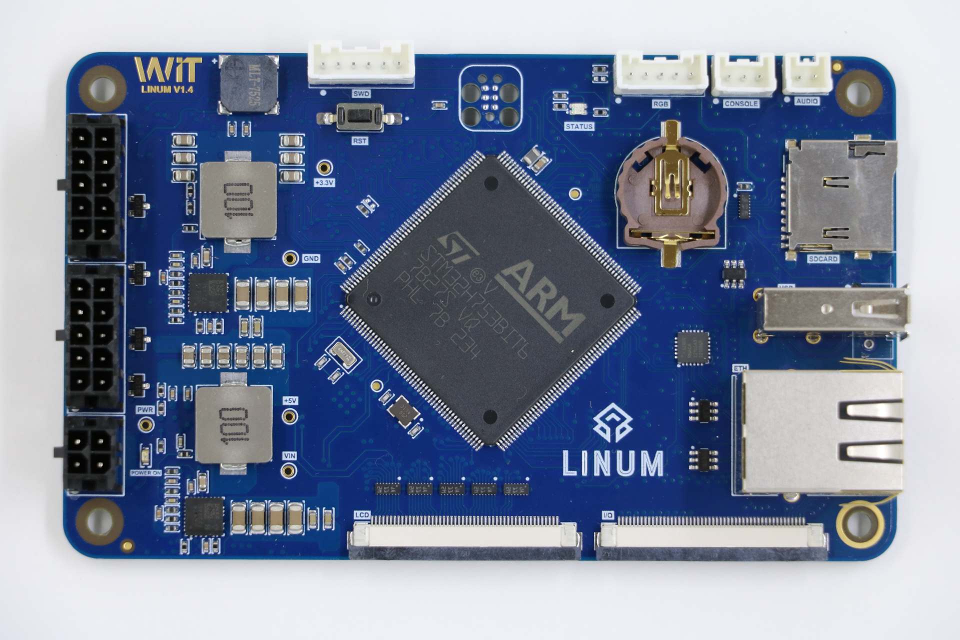
This board was release by Witte Tenology in 2023 and developed based on STM32H753BI microcontroller. The board has 2 expansion connectors used by the LCD display with touchscreen and another for access to other peripherals of microcontroller.
The board features:
: - 8 to 52V power supply - SWD Pins for use as STLink (Pin header) and TC2030-IDC 6-Pin Tag-Connect Plug-of-Nails™ Connector - Crystal for HS 25MHz - Crystal for RTC 32.768KHz - 1 UART serial for debug - 1 Led RGB - 1 Buzzer without internal oscillator - 1 Mono audio up to 3W - 1 Ethernet 10/100 - 1 MicroSD connector supporting 1 or 4-bit bus - 1 USB 2.0 Host/Device - 1 EEPROM memory with 512K bits - 1 External SRAM memory with 8MB - 1 NOR memory with 16MB - 2 On-board RS232 Transceiver with RTS/CTS - 2 On-board RS485 Transceiver - 2 On-board CAN-FD Transceiver
Expansion connector 1 features:
: - 1 Display RBG 565 - 1 Capacitive Touchscreen sensor
Expansion connector 2 features.
: - 1 SPI - 1 I2C - 1 One Wire - 2 DACs - 6 PWM Channels - 10 ADCs
Board documentation: https://wittetech.com/
BOARD-LEDs
The LINUM-STM32H753BI has 3 software controllable LEDs.
LED RGB PINS
LED_R PG2 LED_G PG3 LED_B PB2
UART/USART
The LINUM-STM32H753BI used the USART1 for serial debug messages.
USART1
USART1 PINS
TX PB14 RX PB15
The LINUM-STM32H753BI board has two on-board RS-232 transceiver connected to USART2 and USART3.
USART2 PINS
TXD PD5 RXD PD6 CTS PD3 RTS PD4
USART3 PINS
TXD PB10 RXD PB11 CTS PD11 RTS PD12
The LINUM-STM32H753BI board has two on-board RS-485 transceiver connected to USART4 and USART6.
UART4 PINS
TXD PB9 RXD PB8 DE PA15
USART6 PINS
TXD PC6 RXD PC7 DE PG12
SDMMC
The LINUM-STM32H753BI has one SDCard slot connected as below:
SDMMC1 PINS
SDMMC_D0 PC8 SDMMC_D1 PC9 SDMMC_D2 PC10 SDMMC_D3 PC11 SDMMC_DK PC12
GPIO PINS
SDCARD_DETECTED PG7 SDCARD_PWR_EN PD7
ETHERNET
The LINUM-STM32H753BI has a ethernet connection using the transceiver KSZ8081RNACA.
ETH PINS
ETH_REF_CLK PA1 ETH_MDIO PA2 ETH_CRS_DV PA7 ETH_MDC PC1 ETH_RXD0 PC4 ETH_RXD1 PC5 ETH_TX_EN PG11 ETH_TXD0 PG13 ETH_TXD1 PG14 ETH_CLK PA8 ETH_RESET PI4
CAN-FD
The LINUM-STM32H753BI board has two on-board CAN-FD transceiver connected to FDCAN1 and FDCAN2.
FDCAN1 PINS
TXD PH13 RXD PH14 STD PI2
FDCAN2 PINS
TXD PB13 RXD PB12 STD PE3
USB
The LINUM-STM32H753BI has one usb port.
USB PINS
USB_VBUS PA9 USB_N PA11 USB_P PA12 USB_EN PI12 USB_FLT PI13
QUADSPI
The LINUM-STM32H753BI board has one NOR memory connected to QUADSPI. The NOR memory used is the W25Q128JV with 16MB
QUADSPI PINS
IO0 PF8 IO1 PF9 IO2 PF7 IO3 PF6 CLK PF10 NCS PG6
I2C3
The LINUM-STM32H753BI connects the EEPROM memory and the touchscreen sensor to I2C3.
I2C3 PINS
SCL PH7 SDA PH8
EEPROM MEMORY
EEPROM memory used is the 24LC256 with 256Kb with the control bytes value 0x54.
TOUCHSCREEN SENSOR
The touchscreen sensor used is the FT5X06.
GPIO PINS
TS_RESET PI7 TS_ISR PH9
I2C4
The I2C4 is available for general use on the expansion connector.
I2C4 PINS
SCL PH11 SDA PH12
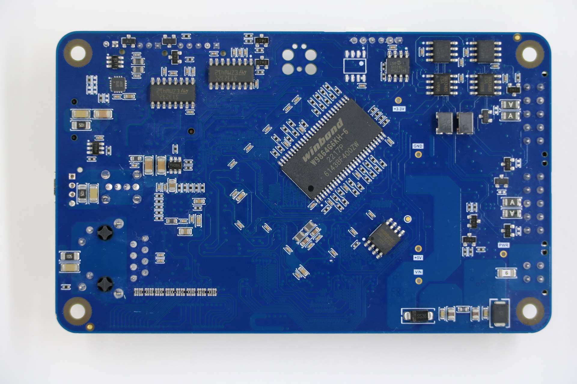
External SDRAM
The LINUM-STM32H753BI has a external SDRAM with 16Mbits connected to FMC peripheral.
FMC PINS
FMC_A0 PJ12 FMC_A1 PF1 FMC_A2 PF2 FMC_A3 PF3 FMC_A4 PF4 FMC_A5 PF5 FMC_A6 PF12 FMC_A7 PF13 FMC_A8 PF14 FMC_A9 PF15 FMC_A10 PG0 FMC_A11 PG1 FMC_BA0 PG4 FMC_BA1 PG5 FMC_D0 PD14 FMC_D1 PD15 FMC_D2 PD0 FMC_D3 PD1 FMC_D4 PE7 FMC_D5 PE8 FMC_D6 PE9 FMC_D7 PE10 FMC_D8 PE11 FMC_D9 PE12 FMC_D10 PE13 FMC_D11 PE14 FMC_D12 PE15 FMC_D13 PD8 FMC_D14 PD9 FMC_D15 PD10 FMC_NBL0 PE0 FMC_NBL1 PE1 FMC_SDCKE0 PC3 FMC_SDCLK PG8 FMC_SDNCAS PG15 FMC_SDNEO PC2 FMC_SDNRAS PF11 FMC_SDNWE PC0
LCD
The LINUM-STM32H753BI use the LTDC to support one LCD with RGB connection.
LTDC PINS
LTDC_B0 PF0 LTDC_B1 PJ13 LTDC_B2 PJ14 LTDC_B3 PJ15 LTDC_B4 PK3 LTDC_B5 PK4 LTDC_B6 PK5 LTDC_B7 PK6 LTDC_CLK PI14 LTDC_DE PK7 LTDC_G0 PJ7 LTDC_G1 PJ8 LTDC_G2 PJ9 LTDC_G3 PJ10 LTDC_G4 PJ11 LTDC_G5 PK0 LTDC_G6 PK1 LTDC_G7 PK2 LTDC_HSYNC PI10 LTDC_R0 PI15 LTDC_R1 PJ0 LTDC_R2 PJ1 LTDC_R3 PJ2 LTDC_R4 PJ3 LTDC_R5 PJ4 LTDC_R6 PJ5 LTDC_R7 PJ6 LTDC_VSYNC PI9 PWM_BACKLIGHT PH6
I2S
The LINUM-STM32H753BI has one I2S output.
I2S2 PINS
I2S2_WS PI0 I2S2_CK PI1 I2S2_SDO PI3
PWM
The LINUM-STM32H753BI has a buzzer without internal oscillator connected to PB7
GPIO PINS
BUZZER PB7
Each linum-stm32h753bi configuration is maintained in a sub-directory and can be selected as follow:
tools/configure.sh linum-stm32h753bi:<subdir>

Where <subdir> is one of the following:
Configuration Directories
nsh
Configures the NuttShell (nsh) located at apps/examples/nsh. This configuration enables a serial console on UART1.
usbnsh
Configures the NuttShell (nsh) located at apps/examples/nsh. This configuration enables a serial console over USB.
After flashing and reboot your board you should see in your dmesg logs:
 sudo dmesg | tail
[ 9180.937813] usb 3-1.1.2: SerialNumber: 0
[ 9180.946974] cdc_acm 3-1.1.2:1.0: ttyACM0: USB ACM device
[ 9715.123387] usb 3-1.1.2: USB disconnect, device number 20
[ 9717.393142] usb 3-1.1.2: new full-speed USB device number 21 using xhci_hcd
[ 9717.494824] usb 3-1.1.2: New USB device found, idVendor=0525, idProduct=a4a7, bcdDevice= 1.01
[ 9717.494834] usb 3-1.1.2: New USB device strings: Mfr=1, Product=2, SerialNumber=3
[ 9717.494837] usb 3-1.1.2: Product: CDC/ACM Serial
[ 9717.494840] usb 3-1.1.2: Manufacturer: NuttX
[ 9717.494842] usb 3-1.1.2: SerialNumber: 0
[ 9717.504192] cdc_acm 3-1.1.2:1.0: ttyACM0: USB ACM device
You may need to press ENTER 3 times before the NSH show up.
modbus_slave
Configures the ModBus RTU Slave located at apps/examples/modbus. This configuration enables a RS485 on USART6.
After configuring the desired pins on menuconfig and wiring the RS485 converter, you can enable the ModBus to respond to queries:
nsh> modbus -e
In your pc you will be able to read the ModBus registers using an application like mbpoll:
mbpoll -a 10 -b 38400 -t 3 -r 1000 -c 4 /dev/ttyUSB1 -R
modbus_master
Configures the ModBus RTU Master located at apps/examples/modbusmaster. This configuration enables a RS485 on USART6.
After configuring the desired pins on menuconfig and wiring the RS485 converter, you can enable the ModBus Master to create queries for device with address 10:
nsh> mbmaster
In your pc you will be able to create a ModBus Slave with address 10 using an application like diagslave:
sudo diagslave -a 10 -b 38400 /dev/ttyUSB0
sdcard
Configures the NuttShell (nsh) and enables SD card support. The board has an onboard microSD slot that should be automatically registered as the block device /dev/mmcsd0 when an SD card is present.
The SD card can then be mounted by the NSH commands:
nsh> mount -t vfat /dev/mmcsd0 /mnt
nsh> mount
nsh> echo "Hello World!!" > /mnt/test_file.txt
nhs> ls /mnt/
test_file.txt
nsh> cat /mnt/test_file.txt
Hello World!!
eeprom
Use dd command to write and read data from EEPROM as below::
nsh> dd if=/dev/console of=/dev/eeprom bs=1 count=35
Witte-Tech Linum-STM32H753BI board
nsh> dd if=/dev/eeprom of=/dev/console bs=4 count=35
Witte-Tech Linum-STM32H753BI board
nsh>
buzzer
This example use the timer 4 with channel 2 to generate a PWM output signal on buzzer pin:
nsh> ls /dev
/dev:
console
null
pwm0
rtc0
ttyS0
nsh> pwm -d 75 -t 3
pwm_main: starting output with frequency: 100 duty: 0000bfff
pwm_main: stopping output
nsh> pwm -f 300 -t 3
pwm_main: starting output with frequency: 300 duty: 0000bfff
pwm_main: stopping output
leds
Example to blink the RBG led of board, using this example the board led status support stop to work:
# turn on led red
printf \x00000001 > /dev/userleds

# turn on led green
printf \x00000002 > /dev/userleds

# turn on led blue
printf \x00000004 > /dev/userleds

# Run blink leds sample
nsh> leds
leds_main: Starting the led_daemon
leds_main: led_daemon started

led_daemon (pid# 3): Running
led_daemon: Opening /dev/userleds
led_daemon: Supported LEDs 0x07
led_daemon: LED set 0x01
nsh> led_daemon: LED set 0x02
led_daemon: LED set 0x03
led_daemon: LED set 0x04
led_daemon: LED set 0x05
led_daemon: LED set 0x06
led_daemon: LED set 0x07
led_daemon: LED set 0x06
led_daemon: LED set 0x05
led_daemon: LED set 0x04
led_daemon: LED set 0x03
led_daemon: LED set 0x02
led_daemon: LED set 0x01
zmodem
This example use the nsh via usb and the SDCard to storage the files exchanged. By default the zmodem lib use the path /tmp to storage the files.
Sending files to target:
# Mount the SDCard at /tmp
nsh> mount -t vfat /dev/mmcsd0 /tmp

# Waiting for a new file.
nsh> rz

# Transmitting a file to target.
my_pc sz --zmodem nuttx_logo.txt > /dev/ttyACM0 < /dev/ttyACM0

# Check if the file was received
nsh> ls -l /tmp
/tmp:
-rw-rw-rw-        1942 nuttx_logo.txt
Transmitting a file to PC:
# Sending the file nuttx_logo.txt to PC
nsh> sz -x 1 /tmp/nuttx_logo.txt
**B00000000000000

# Using zmodem to receive a file from target
my_pc/temp rz > /dev/ttyACM0 < /dev/ttyACM0
Receiving: nuttx_logo.txt
Bytes received:    1942/   1942   BPS:124544

Transfer complete
my_pc/temp ls -l
-rw-------  1 nuttx nuttx    1942 abr  6 16:07 nuttx_logo.txt
If you don't have a SDCard on your board, you can mount the TMPFS at /tmp and transfer files to it, but you cannot transfer big files because TMPFS could use the free RAM of your board:
nsh> mount -t tmpfs /tmp
nxffs
This example use the flash memory W25Q128JV via qspi with the nxffs file system:
NuttShell (NSH) NuttX-12.5.1-RC0
nsh> ls
/:
dev/
w25/
nsh> cd /w25
nsh> echo "hello world!" > message.txt
nsh> ls
/w25:
message.txt
nsh> cat message.txt
hello world!
littlefs
This example use the flash memory W25Q128JV via qspi with the littlefs file system:
NuttShell (NSH) NuttX-12.5.1-RC0
nsh> ls
/:
dev/
w25/
nsh> cd /w25
nsh> mkdir folder1
nsh> cd folder1
nsh> echo "hello world!!!!" > message.txt
nsh> cat message.txt
hello world!!!!
nsh> ls
/w25/folder1:
.
..
message.txt
rndis
This example use ethernet over usb and show how configure ip and download file with wget command from server.
After flash the board check if the linux found and recognized the new network driver:
 sudo dmesg | tail
[30260.873245] rndis_host 3-1.3:1.0 enxa0e0deadbeef: unregister 'rndis_host' usb-0000:00:14.0-1.3, RNDIS device
[30265.461419] usb 3-1.3: new full-speed USB device number 34 using xhci_hcd
[30265.563354] usb 3-1.3: New USB device found, idVendor=584e, idProduct=5342, bcdDevice= 0.01
[30265.563359] usb 3-1.3: New USB device strings: Mfr=1, Product=2, SerialNumber=3
[30265.563361] usb 3-1.3: Product: RNDIS gadget
[30265.563362] usb 3-1.3: Manufacturer: NuttX
[30265.563363] usb 3-1.3: SerialNumber: 1234
[30265.572179] rndis_host 3-1.3:1.0: dev can't take 1558 byte packets (max 660), adjusting MTU to 602
[30265.573517] rndis_host 3-1.3:1.0 eth0: register 'rndis_host' at usb-0000:00:14.0-1.3, RNDIS device, a0:e0:de:ad:be:ef
[30265.584924] rndis_host 3-1.3:1.0 enxa0e0deadbeef: renamed from eth0

 ifconfig
enxa0e0deadbeef: flags=4163<UP,BROADCAST,RUNNING,MULTICAST>  mtu 602
inet 10.42.0.1  netmask 255.255.255.0  broadcast 10.42.0.255
ether a0:e0:de:ad:be:ef  txqueuelen 1000  (Ethernet)
RX packets 87  bytes 10569 (10.5 KB)
RX errors 0  dropped 0  overruns 0  frame 0
TX packets 99  bytes 22896 (22.8 KB)
TX errors 0  dropped 0 overruns 0  carrier 0  collisions 0
OBS: In network settings of PC enable "Shared to other computers"
Configure the IP of target:
nsh> ifconfig eth0 10.42.0.2
nsh> ifconfig
lo  Link encap:Local Loopback at RUNNING mtu 1518
inet addr:127.0.0.1 DRaddr:127.0.0.1 Mask:255.0.0.0

eth0    Link encap:Ethernet HWaddr 00:e0:de:ad:be:ef at UP mtu 576
inet addr:10.42.0.2 DRaddr:10.42.0.1 Mask:255.255.255.0

            IPv4   TCP   UDP  ICMP
Received     012a  0000  0126  0000
Dropped      0004  0000  0000  0000
  IPv4        VHL: 0000   Frg: 0001
  Checksum   0000  0000  0000  ----
  TCP         ACK: 0000   SYN: 0000
              RST: 0000  0000
  Type       0000  ----  ----  0000
Sent         0000  0000  0000  0000
  Rexmit     ----  0000  ----  ----
nsh>
Testing communication with PC using ping command:
nsh> ping 10.42.0.1
PING 10.42.0.1 56 bytes of data
56 bytes from 10.42.0.1: icmp_seq=0 time=0.0 ms
56 bytes from 10.42.0.1: icmp_seq=1 time=0.0 ms
56 bytes from 10.42.0.1: icmp_seq=2 time=0.0 ms
56 bytes from 10.42.0.1: icmp_seq=3 time=0.0 ms
56 bytes from 10.42.0.1: icmp_seq=4 time=0.0 ms
56 bytes from 10.42.0.1: icmp_seq=5 time=0.0 ms
56 bytes from 10.42.0.1: icmp_seq=6 time=0.0 ms
56 bytes from 10.42.0.1: icmp_seq=7 time=0.0 ms
56 bytes from 10.42.0.1: icmp_seq=8 time=0.0 ms
56 bytes from 10.42.0.1: icmp_seq=9 time=0.0 ms
10 packets transmitted, 10 received, 0% packet loss, time 10100 ms
rtt min/avg/max/mdev = 0.000/0.000/0.000/0.000 ms
In your pc you will be able connect to target using telnet and access their shell nsh:
 telnet 10.42.0.2
Trying 10.42.0.2...
Connected to 10.42.0.2.
Escape character is '^]'.

NuttShell (NSH) NuttX-12.5.1
nsh> uname -a
NuttX  12.5.1 c148e8f2af-dirty Apr 28 2024 10:27:50 arm linum-stm32h753bi
nsh> exit
Connection closed by foreign host.
Testing wget to download file from server:
# PC: Creating a http server and sharing local folder.
 sudo python3 -m http.server 80 -d ./

# log of server
Serving HTTP on 0.0.0.0 port 80 (http://0.0.0.0:80/) ...
10.42.0.2 - - [28/Apr/2024 16:14:39] "GET /nuttx_logo.txt HTTP/1.0" 200 -

# Using wget on target
nsh> mount -t tmpfs /tmp
nsh> cd /tmp
nsh> pwd
/tmp
nsh> wget http://10.42.0.1/nuttx_logo.txt
nsh> ls
/tmp:
nuttx_logo.txt
usbmsc-sdcard
This example uses the USB Mass Storage with SD Card.
Enable the USB Mass Storage with the command msconn:
nsh> msconn
mcsonn_main: Creating block drivers
mcsonn_main: handle=0x38003020
mcsonn_main: Bind LUN=0 to /dev/mmcsd0
mcsonn_main: Connected
After that check if your PC recognized the usb driver:
 sudo dmesg | tail
[sudo] password for jaga:
[27219.361934] usbcore: registered new interface driver uas
[27220.378231] scsi 0:0:0:0: Direct-Access     NuttX    Mass Storage     0101 PQ: 0 ANSI: 2
[27220.378646] sd 0:0:0:0: Attached scsi generic sg0 type 0
[27220.379203] sd 0:0:0:0: [sda] 1930240 512-byte logical blocks: (988 MB/943 MiB)
[27220.597414] sd 0:0:0:0: [sda] Write Protect is off
[27220.597419] sd 0:0:0:0: [sda] Mode Sense: 0f 00 00 00
[27220.817620] sd 0:0:0:0: [sda] Write cache: enabled, read cache: enabled, doesn't support DPO or FUA
[27221.265245]  sda: sda1
[27221.266103] sd 0:0:0:0: [sda] Attached SCSI removable disk
[27228.147377] FAT-fs (sda1): Volume was not properly unmounted. Some data may be corrupt. Please run fsck.
OBS: This example disable the macro CONFIG_STM32H7_SDMMC_IDMA, for more information read the file: arch/arm/stm32h7/stm32_sdmmc.c
netnsh
This configuration is focused on network testing using the ethernet periferal:
 nsh> ifconfig
  eth0  Link encap:Ethernet HWaddr 00:e0:de:ad:be:ef at UP mtu 1486
    inet addr:192.168.1.6 DRaddr:192.168.1.1 Mask:255.255.255.0

              IPv4   TCP   UDP  ICMP
  Received     01b9  0025  0194  0000
  Dropped      0000  0000  0000  0000
    IPv4        VHL: 0000   Frg: 0000
    Checksum   0000  0000  0000  ----
    TCP         ACK: 0000   SYN: 0000
                RST: 0000  0000
    Type       0000  ----  ----  0000
  Sent         0028  0025  0003  0000
    Rexmit     ----  0000  ----  ----

  nsh> ping google.com
  PING 142.251.129.110 56 bytes of data
  56 bytes from 142.251.129.110: icmp_seq=0 time=10.0 ms
  56 bytes from 142.251.129.110: icmp_seq=1 time=0.0 ms
  56 bytes from 142.251.129.110: icmp_seq=2 time=0.0 ms
  56 bytes from 142.251.129.110: icmp_seq=3 time=0.0 ms
  56 bytes from 142.251.129.110: icmp_seq=4 time=0.0 ms
  56 bytes from 142.251.129.110: icmp_seq=5 time=0.0 ms
  56 bytes from 142.251.129.110: icmp_seq=6 time=0.0 ms
  56 bytes from 142.251.129.110: icmp_seq=7 time=0.0 ms
  56 bytes from 142.251.129.110: icmp_seq=8 time=0.0 ms
  56 bytes from 142.251.129.110: icmp_seq=9 time=0.0 ms
  10 packets transmitted, 10 received, 0% packet loss, time 10100 ms
  rtt min/avg/max/mdev = 0.000/1.000/10.000/3.000 ms
qencoder
Configures and enables TIM5 on CH1(PA0) and CH2(PH11) to handle Quadrature Encoder:
nsh> qe
qe_main: Hardware initialized. Opening the encoder device: /dev/qe0
qe_main: Number of samples: 0
qe_main:   1. 1
qe_main:   2. 2
qe_main:   3. 3
qe_main:   4. 2
qe_main:   5. 1
sdram
This configuration uses the FMC peripheral to connect to external SDRAM with 8 MB and add it to the nuttx heap.
To test the sdram use the command ramtest:
nsh> free
                total       used       free    maxused    maxfree  nused  nfree
      Umem:    9397168       5488    9391680       5880    8388592     28      5
nsh> ramtest -w -a 0xc0000000 -s 8388608
RAMTest: Marching ones: c0000000 8388608
RAMTest: Marching zeroes: c0000000 8388608
RAMTest: Pattern test: c0000000 8388608 55555555 aaaaaaaa
RAMTest: Pattern test: c0000000 8388608 66666666 99999999
RAMTest: Pattern test: c0000000 8388608 33333333 cccccccc
RAMTest: Address-in-address test: c0000000 8388608
mfrc522
Configures the board to use the SPI4 and enables RFID driver with MFRC522:
nsh> ls /dev/
/dev:
console
null
rfid0
rtc0
ttyS0
nsh> rfid_readuid
Trying to READ: Card is not present!
Trying to READ: Card is not present!
Trying to READ: RFID CARD UID = 0x3DB3F169

======== =====
MFRC522  PINS
======== =====
SCK      PE2
MISO     PE5
MOSI     PE6
CS       PE4
======== =====
lvgl
Configures the board to use display of 7 inch with lvgl example. The touch screen functionality is implemented using the FT5X06 capacitive touch controller connected to I2C3 interface, with interrupt handling configured on pin PH9 for touch event detection.
To verify if the touch controller is functioning correctly, use the tc command.:
nsh> tc 2
tc_main: nsamples: 2
tc_main: Opening /dev/input0
Sample     :
  npoints : 1
Point 1    :
        id : 0
    flags : 19
        x : 0
        y : 52
        h : 0
        w : 0
  pressure : 0
timestamp : 0
Sample     :
  npoints : 1
Point 1    :
        id : 0
    flags : 1a
        x : 0
        y : 52
        h : 0
        w : 0
  pressure : 0
timestamp : 0
Terminating!
To verify if the display is functioning correctly, use the fb command. You should see the display change colors.:
nsh> fb
VideoInfo:
      fmt: 11
    xres: 1024
    yres: 600
  nplanes: 1
noverlays: 1
OverlayInfo (overlay 0):
    fbmem: 0xc0000000
    fblen: 1228800
  stride: 2048
  overlay: 0
      bpp: 16
    blank: 0
chromakey: 0x00000000
    color: 0x00000000
  transp: 0xff
    mode: 0
    area: (0,0) => (1024,600)
    accl: 1
PlaneInfo (plane 0):
    fbmem: 0xc0000000
    fblen: 1228800
  stride: 2048
  display: 0
      bpp: 16
Mapped FB: 0xc0000000
0: (  0,  0) (1024,600)
1: ( 93, 54) (838,492)
2: (186,108) (652,384)
3: (279,162) (466,276)
4: (372,216) (280,168)
5: (465,270) ( 94, 60)
Test finished
Once the fd command works, run the lvgl examples. :
nsh> lvgldemo
nsh> lvgldemo benchmark
WARNING: For this example, the total SDRAM size was reduced from 8M to 6M and the LTDC base address was moved to address 0xC0600000 to avoid video memory invasion since the SDRAM was mapped to use the nuttx heap. If using the example with 2 layers, the reserved value will need to be doubled.
tone
This example demonstrates how to use PWM4 and Timer17 to play music using the Tone library and the board's buzzer.
socketcan
This example demonstrates how to use the CAN-FD peripherals can0 and can1 with the SocketCAN protocol.:
# Configure the can0 and can1 to send messages
nsh> ifup can0
ifup can0...OK
nsh> ifup can1
ifup can1 ...OK
nsh> cansend can0 123#DEADBEEF
nsh> cansend can1 5A1#11.2233.44556677.88

# Reset the board and configure the can0 peripheral to receive messages
nsh> ifup can0
ifup can0...OK
nsh> candump can0
  can0  051   [8]  00 11 22 33 44 55 66 77
  can0  051  [16]  00 11 22 33 44 55 66 77 88 99 AA BB CC DD EE FF