W5500-EVB-Pico
chip:rp2040, ethernet
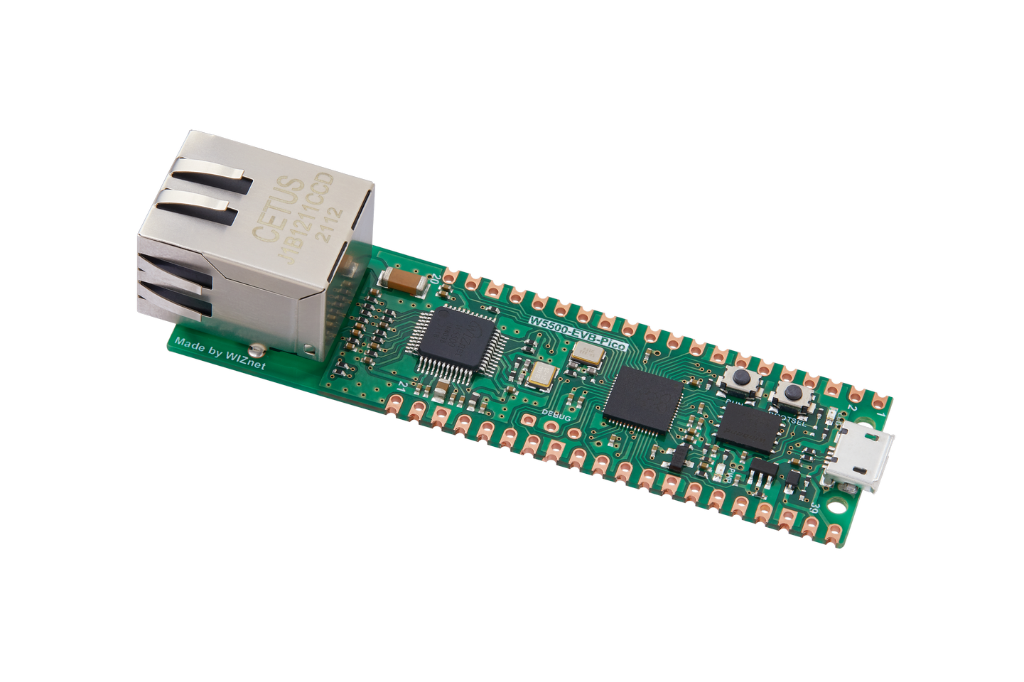
The W5500-EVB-Pico is a microcontroller evaluation board based on the Raspberry Pi RP2040 and fully hardwired TCP/IP controller W5500 -- and basically works the same as Raspberry Pi Pico board but with additional Ethernet via W5500.
Features
- RP2040 microcontroller chip
- Dual-core ARM Cortex M0+ processor, flexible clock running up to 133 MHz
- 264kB of SRAM, and 2MB of on-board Flash memory
- Castellated module allows soldering direct to carrier boards
- USB 1.1 Host and Device support
- Low-power sleep and dormant modes
- Drag & drop programming using mass storage over USB
- 26 multi-function GPIO pins
- 2× SPI, 2× I2C, 2× UART, 3× 12-bit ADC, 16× controllable PWM channels
- Accurate clock and timer on-chip
- Temperature sensor
- Accelerated floating point libraries on-chip
- 8 × Programmable IO (PIO) state machines for custom peripheral support
- Ethernet port via WIZnet W5500, hardwired to SPI0 and two GPIO pins.
Supported RP2040 capabilities
- UART (console port)
- GPIO 0 (UART0 TX) and GPIO 1 (UART0 RX) are used for the console.
- I2C
- SPI (master only)
- DMAC
- PWM
- ADC
- Watchdog
- USB device
- MSC, CDC/ACM serial and these composite device are supported.
- CDC/ACM serial device can be used for the console.
- PIO (RP2040 Programmable I/O)
- Flash ROM Boot
- SRAM Boot
- If Pico SDK is available, nuttx.uf2 file which can be used in BOOTSEL mode will be created.
- Persistent flash filesystem in unused flash ROM
Currently unsupported RP2040 capabilities
- SPI Slave Mode
- SSI
- RTC
- Timers
Serial Console
The board is configured to use the USB connection as the serial console.
Buttons and LEDs
User LED controlled by GPIO25.
A BOOTSEL button, which if held down when power is first applied to the board, will cause the RP2040 to boot into programming mode and appear as a storage device to a computer connected via USB. Saving a .UF2 file to this device will replace the Flash ROM contents on the RP2040.
Pin Mapping
Pads numbered anticlockwise from USB connector.
Pad Signal Notes
1 GPIO0 Default TX for UART0 serial console 2 3 4 5 6 7 8 9 10 11 12 13 14 15 16 17 18 19 20 GPIO1 Ground GPIO2 GPIO3 GPIO4 GPIO5 Ground GPIO6 GPIO7 GPIO8 GPIO9 Ground GPIO10 GPIO11 GPIO12 GPIO13 Ground GPIO14 GPIO15 Default RX for UART1 serial console 21 GPIO16 W5500 MISO 22 23 GPIO17 Ground W5500 CSn 24 GPIO18 W5500 SCLK 25 GPIO19 W5500 MOSI 26 GPIO20 W5500 RSTn 27 28 29 30 GPIO21 Ground GPIO22 Run W5500 INTn 31 GPIO26 ADC0 32 GPIO27 ADC1 33 AGND Analog Ground 34 35 GPIO28 ADC_VREF ADC2 36 3V3 Power output to peripherals 37 38 3V3_EN Ground Pull to ground to turn off. 39 VSYS +5V Supply to board 40 VBUS Connected to USB +5V
Other RP2040 Pins
Signal Notes
GPIO23 Output - Power supply control. GPIO24 Input - High if USB port or Pad 40 supplying power. GPIO25 Output - On board LED. ADC3 Input - Analog voltage equal to one third of VSys voltage.
Separate pins for the Serial Debug Port (SDB) are available
Power Supply
The W5500-EVB-Pico can be powered via the USB connector, or by supplying +5V to pin 39. The board had a diode that prevents power from pin 39 from flowing back to the USB socket, although the socket can be power via pin 30.
The W5500-EVB-Pico chip run on 3.3 volts. This is supplied by an onboard voltage regulator. This regulator can be disabled by pulling pin 37 to ground.
The regulator can run in two modes. By default the regulator runs in PFM mode which provides the best efficiency, but may be switched to PWM mode for improved ripple by outputting a one on GPIO23.
Installation
- Download Raspberry Pi Pico SDK
<!-- --> git clone -b 2.0.0 https://github.com/raspberrypi/pico-sdk.git
- Set PICO_SDK_PATH environment variable
<!-- --> export PICO_SDK_PATH=<absolute_path_to_pico-sdk_directory>
- Configure and build NuttX
<!-- --> git clone https://github.com/apache/nuttx.git nuttx
git clone https://github.com/apache/nuttx-apps.git apps
cd nuttx
make distclean
./tools/configure.sh w5500-evb-pico:usbnsh
make V=1
- Connect W5500-EVB-Pico board to USB port while pressing BOOTSEL. The board will be detected as USB Mass Storage Device. Then copy "nuttx.uf2" into the device. (Same manner as the standard Pico SDK applications installation.)
- [usbnsh]{.title-ref} configuration provides the console access by USB CDC/ACM serial devcice. The console is available by using a terminal software on the USB host.
Configurations
usbnsh
USB CDC/ACM serial console with NuttShell. TCP/IPv4 & IPv6 networking is supported via the Ethernet port.
License exceptions
The following files are originated from the files in Pico SDK. So, the files are licensed under 3-Clause BSD same as Pico SDK.
Created by referring to the Pico SDK clock initialization
- arch/arm/src/rp2040/rp2040_clock.c
- arch/arm/src/rp2040/rp2040_pll.c
- arch/arm/src/rp2040/rp2040_xosc.c
Providing an API similar to the Pico SDK's hardware_pio API
- arch/arm/src/rp2040/rp2040_pio.c
- arch/arm/src/rp2040/rp2040_pio.h
- arch/arm/src/rp2040/rp2040_pio_instructions.h
Generated from rp2040.svd originally provided in Pico SDK
- arch/arm/src/rp2040/hardware/*.h