Adafruit Feather RP2040
chip:rp2040
The Feather RP2040 is a general purpose RP2040 board supplied by Adafruit.
See the Adafruit website for information about Adafruit Feather RP2040.
Features
- RP2040 microcontroller chip
- Dual-core ARM Cortex M0+ processor, flexible clock running up to 133 MHz
- 264kB of SRAM, and 8MB of on-board Flash memory
- Castellated module allows soldering direct to carrier boards
- USB Host and Device support via type C connector.
- Low-power sleep and dormant modes
- Drag & drop programming using mass storage over USB
- 26 multi-function GPIO pins
- 2× SPI, 2× I2C, 2× UART, 3× 12-bit ADC, 16× controllable PWM channels
- Accurate clock and timer on-chip
- Temperature sensor
- Accelerated floating point libraries on-chip
- 8 × Programmable IO (PIO) state machines for custom peripheral support
- LiPoly Battery connector
Serial Console
By default a serial console appears on pins 14 (RX GPIO0) and pin 15 (TX GPIO1). This console runs a 115200-8N1.
The board can be configured to use the USB connection as the serial console.
Buttons and LEDs
User LED controlled by GPIO13.
A ws2812 (NeoPixel) smart RGB LED controlled by GPIO16.
An LED (CHG LED) that indicates the charging status of connected LiPo cell.
There is a BOOT button which if held down when power is first applied or the RESET button is pressed will cause the RP2040 to boot into program mode and appear as a storage device to a USB connector. Saving a .UF2 file to this device will replace the Flash ROM contents on the RP2040.
A RESET button that allows rebooting the board without disconnecting the power.
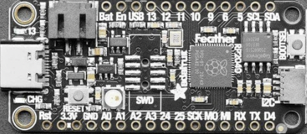
Pin Mapping
Pads numbered anticlockwise from USB connector.
Pad Signal Notes
1 Reset Pull to ground to reset the RP2040 processor. 2 3.3V Power out to peripherals. 3 4 3.3V Ground Power out to peripherals. 5 GPIO26 ADC0 6 GPIO27 ADC1 7 GPIO28 ADC2 8 9 10 11 12 13 GPIO29 GPIO24 GPIO25 GPIO18 GPIO19 GPIO20 ADC3 14 GPIO1 Default RX for UART0 serial console 15 16 17 18 19 20 21 22 23 24 25 GPIO0 GPIO6 GPIO2 GPIO3 GPIO7 GPIO8 GPIO9 GPIO10 GPIO11 GPIO12 GPIO13 Default TX for UART0 serial console 26 VBUS Connected to USB +5V 27 EN Pull to ground to turn off 3.3V regulator. 28 VBAT Connected to LiPo battery 3.3V.
The board has a STEMMA QT connector that is also connected to pins GPIO2 (I2C1 SDA) and GPIO3 (I2C1 SDA).
The board has a two pin JST PH socket that accepts a single 3.3V LiPo cell. The cell connected to this port can be charged by connecting the board to a USB power supply.
There are solder pads on the board that allow the addition of a 10-pin serial debug (SWD) connector.
Power Supply
The Raspberry Pi Pico can be powered via the USB connector, or by supplying +5V to pin 39. The board had a diode that prevents power from pin 39 from flowing back to the USB socket, although the socket can be power via pin 30.
The Raspberry Pi Pico chip run on 3.3 volts. This is supplied by an onboard voltage regulator. This regulator can be disabled by pulling pin 37 to ground.
The regulator can run in two modes. By default the regulator runs in PFM mode which provides the best efficiency, but may be switched to PWM mode for improved ripple by outputting a one on GPIO23.
Supported Capabilities
NuttX supports the following RP2040 capabilities:
- UART (console port)
- GPIO 0 (UART0 TX) and GPIO 1 (UART0 RX) are used for the console.
- I2C
- SPI (master only)
- DMAC
- PWM
- ADC
- Watchdog
- USB device
- MSC, CDC/ACM serial and these composite device are supported.
- CDC/ACM serial device can be used for the console.
- PIO (RP2040 Programmable I/O)
- Flash ROM Boot
- SRAM Boot
- If Pico SDK is available, nuttx.uf2 file which can be used in BOOTSEL mode will be created.
- Persistent flash filesystem in unused flash ROM
- WiFi wireless communication
There is currently no direct user mode access to these RP2040 hardware features:
- SPI Slave Mode
- SSI
- RTC
- Timers
NuttX also provide support for these external devices:
- BMP180 sensor at I2C0 (don't forget to define I2C0 GPIOs at "I2C0 GPIO pin assign" in Board Selection menu)
- INA219 sensor / module (don't forget to define I2C0 GPIOs at "I2C0 GPIO pin assign" in Board Selection menu)
- SHT4X sensor at I2C0
- Pico Display Pack (ST7789 LCD)
- RGB leds and buttons are not supported yet.
- Pico Audio Pack (PCM5100A I2S DAC)
- I2S interface is realized by PIO.
- WS2812 smart pixel support
Installation
- Download Raspberry Pi Pico SDK.
git clone -b 2.0.0 https://github.com/raspberrypi/pico-sdk.git- Download and install picotool
Instructions can be found here: https://github.com/raspberrypi/picotool
If you are on Arch Linux, you can install the picotool through the AUR:
yay -S picotool- Set PICO_SDK_PATH environment variable
export PICO_SDK_PATH=<absolute_path_to_pico-sdk_directory>- Configure and build NuttX
 git clone https://github.com/apache/nuttx.git nuttx
 git clone https://github.com/apache/nuttx-apps.git apps
 cd nuttx
 make distclean
 ./tools/configure.sh raspberrypi-pico-w:nsh
 make V=1
Connect the Adafruit Feather RP2040 board to the USB port while pressing BOOTSEL. The board will be detected as USB Mass Storage Device. Then copy "nuttx.uf2" into the device. (Same manner as the standard Pico SDK applications installation.)
To access the console, GPIO 0 and 1 pins must be connected to the device such as USB-serial converter.
[usbnsh]{.title-ref} configuration provides the console access by USB CDC/ACM serial device. The console is available by using a terminal software on the USB host.
Configurations
audiopack
NuttShell configuration (console enabled in UART0, at 115200 bps) with support for NXPlayer audio player.
Pico Audio Pack support. See the following page for connection: https://shop.pimoroni.com/products/pico-audio-pack SD card interface is also enabled.
composite
NuttShell configuration (console enabled in UART0, at 115200 bps) with support for CDC/ACM with MSC USB composite driver. conn command enables the composite device.
displaypack
NuttShell configuration (console enabled in USB Port, at 115200 bps) supporting ST7789 video display.
See the following page for connection: https://shop.pimoroni.com/products/pico-display-pack
enc28j60
NuttShell configuration (console enabled in UART0, at 115200 bps) with support for ENC28J60.
ENC28J60 SPI ethernet controller supports:
- IP address is configured by DHCP.
- DNS address is 8.8.8.8 (CONFIG_NETINIT_DNSIPADDR)
- NTP client is enabled.
ENC28J60 Raspberry Pi Pico W
GND GND (Pin 3 or 38 or ...) 3.3V 3V3 OUT (Pin 36) SI GP15 (SPI1 TX) (Pin 20) SCK GP14 (SPI1 SCK) (Pin 19) CS GP13 (SPI1 CSn) (Pin 17) SO GP12 (SPI1 RX) (Pin 16) INT GP11 (Pin 15) RESET GP10 (Pin 14)
: ENC28J60 connections
lcd1602
NuttShell configuration (console enabled in UART0, at 115200 bps) with support for LCD1602 Segment LCD Display (I2C).
PCF8574 BackPack Raspberry Pi Pico W
GND GND (Pin 3 or 38 or ...) VCC 5V Vbus (Pin 40) SDA GP4 (I2C0 SDA) (Pin 6) SCL GP5 (I2C0 SCL) (Pin 7)
: LCD1602 connections
nsh
Basic NuttShell configuration (console enabled in UART0, at 115200 bps).
nsh-flash
Basic NuttShell configuration (console enabled in UART0, at 115200 bps with SMART flash filesystem.
nshsram
NuttShell configuration (console enabled in UART0, at 115200 bps) with interrupt vectors in RAM.
smp
Basic NuttShell configuration (console enabled in UART0, at 115200 bps) with both ARM cores enabled.
spisd
NuttShell configuration (console enabled in UART0, at 115200 bps) with SPI SD card support enabled.
SD card slot Raspberry Pi Pico W
DAT2 Not connected DAT3/CS GP17 (SPI0 CSn) (Pin 22) CMD /DI GP19 (SPI0 TX) (Pin 25) VDD 3V3 OUT (Pin 36) CLK/SCK GP18 (SPI0 SCK) (Pin 24) VSS GND (Pin 3 or 38 or ...) DAT0/DO GP16 (SPI0 RX) (Pin 21) DAT1 Not connected
: spisd connections
Card hot swapping is not supported.
ssd1306
NuttShell configuration (console enabled in UART0, at 115200 bps) with support for SSD1306 OLED display (I2C) test configuration.
SSD1306 Raspberry Pi Pico W
GND GND (Pin 3 or 38 or ...) VCC 3V3 OUT (Pin 36) SDA GP4 (I2C0 SDA) (Pin 6) SCL GP5 (I2C0 SCL) (Pin 7)
: SSD1306 connections
st7735
NuttShell configuration (console enabled in UART0, at 115200 bps) with support for ST7735 SPI LCD.
st7735 Raspberry Pi Pico W
GND GND (Pin 3 or 38 or ...) VCC 5V Vbus (Pin 40) SDA GP15 (SPI1 TX) (Pin 20) SCK GP14 (SPI1 SCK) (Pin 19) CS GP13 (SPI1 CSn) (Pin 17) AO(D/C) GP12 (SPI1 RX) (Pin 16) BL GP11 (Pin 15) RESET GP10 (Pin 14)
: ST7735 connections
usbmsc
NuttShell configuration (console enabled in UART0, at 115200 bps) with support for USB MSC and CDC/ACM.
msconn and sercon commands enable the MSC and CDC/ACM devices. The MSC support provides the interface to the SD card with SPI, so the SD card slot connection like spisd configuration is required.
usbnsh
Basic NuttShell configuration using CDC/ACM serial (console enabled in USB Port, at 115200 bps).
waveshare-lcd-1.14
NuttShell configuration (console enabled in UART0, at 115200 bps) with support for st7789.
waveshare-lcd-1.3
NuttShell configuration (console enabled in UART0, at 115200 bps) with support for usbmsc.
License exceptions
The following files are originated from the files in Pico SDK. So, the files are licensed under 3-Clause BSD same as Pico SDK.
- arch/arm/src/rp2040/rp2040_clock.c
- arch/arm/src/rp2040/rp2040_pll.c
- arch/arm/src/rp2040/rp2040_xosc.c
- These are created by referring the Pico SDK clock initialization.
- arch/arm/src/rp2040/rp2040_pio.c
- arch/arm/src/rp2040/rp2040_pio.h
- arch/arm/src/rp2040/rp2040_pio_instructions.h
- These provide the similar APIs to Pico SDK's hardware_pio APIs.
- arch/arm/src/rp2040/hardware/*.h
- These are generated from rp2040.svd originally provided in Pico SDK.